575: Difference between revisions
No edit summary |
No edit summary |
||
| (96 intermediate revisions by 10 users not shown) | |||
| Line 1: | Line 1: | ||
[[ | {{Instrument Sidebar | ||
|manufacturer=Tektronix | |||
|class=Curve Tracer | |||
|model=575 | |||
|summary=Curve tracer for transistors | |||
|image=Tek_575-Front-Trace.jpeg | |||
|caption=Tektronix 575 | |||
|introduced=1957 | |||
|discontinued=1972 | |||
|designers=John Kobbe | |||
|manuals= | |||
* [[Media:070-255.pdf|Tektronix 575 and 175 Manual]] | |||
* [[Media:tek-575-122c.pdf|Tektronix 575 with Mod 122C Manual]] | |||
* [[Media:Tek 575 rackmount.pdf|Tektronix 575 rackmount images]] | |||
<small> | |||
'''Modifications''' | |||
* [[Media:Tek_575_Mod_Summaries.pdf|Tektronix 575 Modification Summaries]] / <small> [[Media:Tektronix575ModSummaries.pdf|Tektronix 575 Modification Summaries]]</small> | |||
* [[Media:Tektronix_575_mod_122c_modifications.pdf|Mod 122C Kit Manual]] | |||
* [[Media:Tek 575mod122c correspondence.pdf|Correspondence Regarding 575 Mod 122A and C]] | |||
* [[Media:Tek 575 mod 122D.pdf|Modification 122D]] | |||
* [[Media:Tek 575 mod 122c description 1961.pdf|Tektronix 575 Mod 122C Description 1961]] | |||
* [[Media:Tek 575 122c instructions for custom instruments.pdf|Tektronix 575 Mod 122C Instructions for Custom Instruments]] | |||
* [[Media:Tek 575 mod 122c instructions.pdf|Tektronix 575 Mod 122C Instructions]] | |||
* [[Media:Tek 575 122c parts list.pdf|Tektronix 575 Mod 122C Parts List]] | |||
* [[Media:040-0223-00.pdf|Mod M5272: Silicon Rectifier]] | |||
* [[Media:040-0276-00.pdf|Mod 122C: Increased collector volts]] | |||
* [[Media:050-0021-00.pdf|Mod M2058, M10070, M8244: Base Step Generator Polarity Switch Replacement]] | |||
* [[Media:050-0070-01.pdf|Mod M6375: Transistor Selector Switch Replacement]] | |||
* [[Media:050-0065-00.pdf|Mod M3873: Precision Resistor Replacement]] | |||
* [[Media:050-0104-00.pdf|Mod for Horizontal Volts/Div Switch Replacement]] | |||
* [[Media:050-0218-00.pdf|Mod for P7 CRT Replacement]] | |||
* [[Media:050-0218-11.pdf|Mod for P11 CRT Replacement]] | |||
* [[Media:050-0218-12.pdf|Mod for P31 CRT Replacement]] | |||
* [[Media:050-0383-00.pdf|Mod M12361: Horizontal and Vertical Amplifier Tube Replacement]] | |||
* [[Media:Jan 1959 tek 575 fcp with cal check.pdf]] | |||
* [[Media:Tek 575 rackmount westinghouse.pdf|Rackmount 575]] | |||
'''Calibration''' | |||
* [[Media:tek_575_fac_cal.pdf|Tektronix 575 Factory Calibration Procedure]] | |||
* [[Media:tek_3-terminal_adapter_013-0069-00.pdf|013-0069-00 3-Terminal Adapter]] | |||
* [[Media:Tek 575 cal outline.pdf]] | |||
'''Miscellaneous''' | |||
* [[Media:Nuvistor checking procedure with 575.pdf|Nuvistor Checking Procedure with 575]] | |||
* [[Media:575_Usage_-_Some_Transistor_Measurements_Using_the_575.pdf|Some Transistor Measurements Using the Type 575]] | |||
* [[Media:Tek 175 higher voltage discussion.pdf|Discussions of Modification to 575 for Higher Voltage]] | |||
* [[Media:Tek 575a discussion.pdf|Discussion of Possible 575A]] | |||
</small> | |||
}} | |||
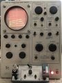
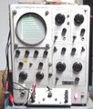
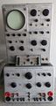
The '''Tektronix 575''' is a curve tracer for transistors, [[introduced in 1957|introduced in March 1957]]. | The '''Tektronix 575''' is a curve tracer for transistors, [[introduced in 1957|introduced in March 1957]]. | ||
== X-Y display == | It can be thought of as being composed of three modules: an X-Y display, a step source, and a collector sweep source. | ||
The vertical and horizontal amplifiers are very similar, | |||
Unlike later curve tracers, the 575 can optionally display base voltage on the vertical axis. | |||
{{BeginSpecs}} | |||
{{Spec | Collector Sweep | 0−200 V minimum peak with 1 A current curves, 0−20 V minimum peak with 20 A current curves }} | |||
{{Spec | Vertical Display | I<sub>C</sub> 0.01 mA/div to 1 A/div ±3% in 16 Steps, or U<sub>B</sub> 0.01 V/div to 0.5 V/div ±3% in 6 Steps }} | |||
{{Spec | Horizontal Display | U<sub>C</sub> 0.01 V/div to 20 V/div ±3% in 11 Steps, or U<sub>B</sub> 0.01 V/div to 0.5 V/div ±3% in 6 Steps }} | |||
{{Spec | CRT | [[T0520]], P1 phosphor, P2/P7/P11 on request; 4.2 kV acceleration }} | |||
{{Spec | Power | 105−125 V or 210−250 V<sub>AC</sub>, 50 to 60 Hz; 200 W in standby, 400 W max; thermal cutoff}} | |||
{{Spec | Size | (W/L/H) 13" × 24" × 16¾" }} | |||
{{Spec | Weight | ~30 kg (70 lb) }} | |||
{{EndSpecs}} | |||
==Links== | |||
* [https://lazyelectrons.wordpress.com/2018/10/13/tektronix-575-curve-tracer-restore/ A Tek 575 Restoration with video] | |||
* [https://w140.com/tek_575_use.pdf ''A Power Curve Tracer At Surplus Prices''], by [[Dennis Feucht]] | |||
* [https://www.oscilloscopemuseum.com/oscilloscope-tektronix-575-s1957.html Tek 575 @ oscilloscopemuseum.com] | |||
* [https://techchannel.att.com/play-video.cfm/2011/7/1/AT&T-Archives-Microworld Tek 575 in AT&T film "Microworld" (1976)] at ~6:00 | |||
* [http://www.ke5fx.com/A_VTCT_Adapter_for_All_Tektronix_SCTs_W7PF.pdf Dennis Tillman: An Inexpensive Vacuum Tube Curve Tracer Adapter for All Tektronix Semiconductor Curve Tracers] | |||
* [https://www.youtube.com/watch?v=Ix7ju0Q8YZg Zenwizard Studios - Curve Tracer Basics] | |||
* [https://www.youtube.com/watch?v=Wpok66re3G0 Zenwizard Studios - Zen's Curve Tracer Buying Guide] | |||
{{Documents|Link=575}} | |||
{{Documents|Link=Curve tracers}} | |||
==History== | |||
[https://vintagetek.org/my-early-tektronix-days-by-john-kobbe-2/ John Kobbe says]: | |||
<blockquote> | |||
When transistors started to become practical, Tek sent [[Bill Polits]] to Michigan, for a 2 week primer on transistors. | |||
He in turn communicated it to the rest of us who were interested. That called for a transistor curve tracer. | |||
It used a similar step generator as the tube curve tracer but otherwise needed mostly new circuits. | |||
I remember a day at the beach, I was trying to hide from the sun while everyone else was getting their sunburn. | |||
I dug the sand out from under our new 1954 Chevy, got comfortable and figured out the circuits for the curve tracer soon to become the 575. | |||
[[Deane Kidd]] did the hard part when he designed the switches. | |||
</blockquote> | |||
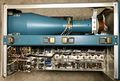
==Internals== | |||
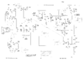
=== X-Y display === | |||
The vertical and horizontal amplifiers are very similar, | |||
using the two halves of a [[6CG7]] dual-triode tube as the output amplifier. | using the two halves of a [[6CG7]] dual-triode tube as the output amplifier. | ||
The CRT has | The CRT has −1700 V on the cathode and +2500 V on the anode. | ||
The HV power supply uses two [[5642]] rectifier tubes. | The HV power supply uses two [[5642]] rectifier tubes. | ||
== Step Source == | It is possible to use the 575 as an X-Y monitor. The vertical and horizontal | ||
This uses a gated | range switches have settings for external input, at 0.1 V/div sensitivity. | ||
The result is a staircase waveform, which generates different traces in | |||
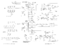
=== Step Source === | |||
This uses a gated Miller integrator to generate controlled steps. | |||
The result is a staircase waveform, which generates different traces in the family of I-V curves of the transistor. | |||
== | === Power Supplies === | ||
Power from the mains goes through an isolation transformer and a variac and is rectified by germanium diodes to produce the collector sweep voltage. | The 575 contains three separate power supplies: | ||
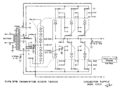
* A '''main power supply''' around T601 (120-095 and, later, [[120-0095-01]]), supplying power to the amplifiers and step generator in the 575. | |||
:This power supply follows the standard 500-series power supply design. | |||
:In addition to heater power, it provides −150 V, +100 V, +300 V regulated and +400 V unregulated output. | |||
:It uses a mix of tubes and silicon or [[selenium rectifiers]] (earlier S/N) for rectification. | |||
:The −150 V and +400 V unregulated/+300 V regulated rails are supplied through [[6BW4]] full wave rectifier tubes, the +100 V circuits through silicon diodes/[[selenium rectifiers]]. | |||
:The −150 V rail is the main reference supply. Its regulator uses a [[5651]] voltage reference, a [[6AN8]] as the comparator/error amplifier, and a [[12B4]] as series pass tube. | |||
:The +100 V regulator uses a [[6080]] series pass tube and a [[6AU6]] tube as the error amplifier. | |||
:The +300 V regulator is similar to the +100 V circuit, except that it uses a [[12B4]] series pass tube. | |||
:Unregulated +400 V is provided for the CRT HV Oscillator. | |||
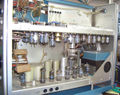
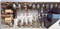
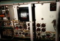
* A '''high-voltage supply''' around T801, supplying the CRT voltages, +2300 V for the CRT anode and −1700 V for the CRT cathode. | |||
:This HV power supply uses a [[6AQ5]] as the HV oscillator tube, and a [[12AU7]] as the feedback/error amplifier. | |||
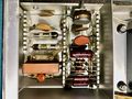
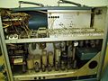
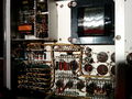
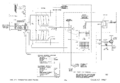
* A '''collector sweep supply''' for the device under test. | |||
: Power from the mains goes through an isolation transformer (T701) and a variac (T702) and is rectified by germanium diodes to produce the collector sweep voltage. | |||
: The isolation transformer has two pairs of secondary taps, one for high voltage (0 to 200 V) and low current, the other for low voltage (0 to 20 V) and high current. | |||
: The maximum power that can be delivered to the transistor in either mode is approximately 200 Watts. | |||
: 575s with Mod 122C offer extended collector sweep voltage to 400 V. | |||
575 | === Rectifiers === | ||
Early 575 versions used [[selenium rectifiers]]. | |||
A kit for conversion to silicon diodes was available and is documented in the back of the manual. | |||
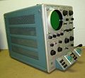
== Type 175 High Current Adaptor == | == Type 175 High Current Adaptor == | ||
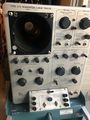
The 575 can be paired with a [[175]] for high current device measurements | [[File:Tek 575 on 175.jpg | thumb | right | 575 on top of a [[175]]]] | ||
The 575 can be paired with a [[175]] for high current device measurements. | |||
== | ==See Also== | ||
* [[067-078]] | |||
* [[Nuvistor Checker-Balancer]] | |||
==Pictures== | |||
<gallery> | |||
Tek 575 npn traces.jpg | |||
Tek_575-Front-Trace.jpeg | NPN Trace | |||
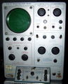
Tek 575 tq.jpg |575 w/o Mod 122C | |||
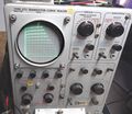
575_122C.JPG|575 w Mod 122C | |||
Tek_757_Cart.jpg | 575 In a Cart | |||
Tek 575 mod 118 1.jpg|Tektronix 575 Mod 118 | |||
Tek 575 mod 118 2.jpg|Tektronix 575 Mod 118 | |||
USA Tektronix 575 Front RAW.jpg | |||
Tek 575 8250.JPG | |||
Tek_575-Top.jpeg | Top | |||
Tek_575_Chart.png | 575 Load Resistance Chart | |||
Tek 575 top.jpg | |||
Tek_575-Rear.jpeg | Rear | |||
Tek 575 rear.jpg | |||
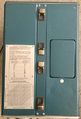
Tek_575_TestPanel.jpg | 575 Test Panel | |||
Tek 575 transistor sockets.jpg | Test Sockets | |||
Tek 575 pnp trace.jpg | |||
Tek 575 display.jpg | |||
Tek 575 tunnel diode.jpg|575 testing a tunnel diode | |||
Tek_575_NPN.jpg | NPN - Curve of 2N3904 | |||
Tek_575_PNPCurve_2N2207.jpg | PNP - Curve of 2N2207 | |||
Tek_575_5651_VRCurve.jpg | 5651 VR Tube in 575 | |||
Tek_575_NPN-hfe_Curve.jpg | hFE curve of a 2N3904 in 575 | |||
Tek 575 with 175.jpg|575 with 175 | |||
</gallery> | |||
===Internal=== | |||
<gallery> | <gallery> | ||
Tek_575_NoCRT.jpg | Front without CRT | |||
Tek_575-Internal-Top.jpeg | Internal Top | |||
Tek_575_Top.jpg | Top View without Support Bar | |||
Tek-575-Internal-Bottom.jpeg | Internal Bottom | |||
Tek_575-Internal-RHS.jpeg | Internal RHS | |||
Tek_575-Internal-LHS.jpeg | Internal LHS | |||
575 int 1.jpg | |||
575 int 2.jpg | |||
575 int 3.jpg | |||
USA Tektronix 575 InsideR0.jpg | |||
Tek 575 left.jpg | |||
Tek 575 right.jpg | |||
Tek_575-HVSection.jpeg | HV Section | |||
Tek 575 hvps 1.jpg | High-Voltage Power Supply | |||
Tek 575 CollectorSweep.jpg | Collector sweep germanium rectifier and dissipation resistor stack | |||
Tek_575_Rectifier.jpg | Rectifiers - Silicon Diode Version | |||
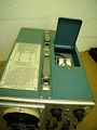
Tek_575_Rear_FanRmvd.jpg | Rear View, Air-filter/Fan Removed. | |||
Tek_575_CRTConn.jpg | Def Plate Connections | |||
575 int 4.jpg | |||
575 int 5.jpg | |||
Tek 575 internal.jpg | |||
Tek 575 Side.jpg | Internal Side View | |||
Tek_575_Underside.jpg | Bottom#1 | |||
Tek 575 bottom.jpg | Bottom#2 | |||
Tek 575 bottom rear.jpg | Bottom Rear | |||
Tube_154-0343-00.jpg | CRT of 575, Type [[T0520]] | |||
Tek_575_Live.jpg | Inside view of a live 575 | |||
</gallery> | |||
===Schematics=== | |||
<gallery> | |||
Tek 575 collector sweep2.png|Unmodified Collector Supply | |||
Tek 575 122c-collector supply.png|Collector Supply Rectifier with MOD122C | |||
Tek 575 ps.png|Main Power Supply | |||
Tek 575 step gen.png|Step Generator | |||
Tek 575 amplifiers.png|Amplifiers | |||
Tek 575 crt circuit.png|CRT Circuit | |||
</gallery> | </gallery> | ||
==Components== | |||
{{Parts|575}} | |||
[[Category:Curve tracers]] | [[Category:Curve tracers]] | ||
Latest revision as of 05:41, 14 March 2024

The Tektronix 575 is a curve tracer for transistors, introduced in March 1957.
It can be thought of as being composed of three modules: an X-Y display, a step source, and a collector sweep source.
Unlike later curve tracers, the 575 can optionally display base voltage on the vertical axis.
Key Specifications
| Collector Sweep | 0−200 V minimum peak with 1 A current curves, 0−20 V minimum peak with 20 A current curves |
|---|---|
| Vertical Display | IC 0.01 mA/div to 1 A/div ±3% in 16 Steps, or UB 0.01 V/div to 0.5 V/div ±3% in 6 Steps |
| Horizontal Display | UC 0.01 V/div to 20 V/div ±3% in 11 Steps, or UB 0.01 V/div to 0.5 V/div ±3% in 6 Steps |
| CRT | T0520, P1 phosphor, P2/P7/P11 on request; 4.2 kV acceleration |
| Power | 105−125 V or 210−250 VAC, 50 to 60 Hz; 200 W in standby, 400 W max; thermal cutoff |
| Size | (W/L/H) 13" × 24" × 16¾" |
| Weight | ~30 kg (70 lb) |
Links
- A Tek 575 Restoration with video
- A Power Curve Tracer At Surplus Prices, by Dennis Feucht
- Tek 575 @ oscilloscopemuseum.com
- Tek 575 in AT&T film "Microworld" (1976) at ~6:00
- Dennis Tillman: An Inexpensive Vacuum Tube Curve Tracer Adapter for All Tektronix Semiconductor Curve Tracers
- Zenwizard Studios - Curve Tracer Basics
- Zenwizard Studios - Zen's Curve Tracer Buying Guide
Documents Referencing 575
| Document | Class | Title | Authors | Year | Links |
|---|---|---|---|---|---|
| Service Scope 50 Jun 1968.pdf | Article | Measuring FETs with a Type 575 | 1968 | 575 | |
| Tekscope 1969 V1 N5 Oct 1969.pdf | Article | Troubleshooting the Sweep Ciruits | Charles Phillips | 1969 | 575 • 576 • Curve tracers |
| Tekscope 1975 V7 N3.pdf | Article | A Potpourri of Modifications and Service Hints | 1975 | 465 • 5L4N • 464 • 466 • 575 • 576 • 577 • TM504 |
Documents Referencing Curve tracers
| Document | Class | Title | Authors | Year | Links |
|---|---|---|---|---|---|
| 062-1009-00.pdf | Book | Measurement Concepts: Semiconductor Device Measurements | John Mulvey | 1969 | Curve tracers • Tunnel diodes |
| Tekscope 1969 V1 N1 Feb 1969.pdf | Article | Curve Tracing Displays | 1969 | Curve tracers • 576 | |
| Tekscope 1969 V1 N5 Oct 1969.pdf | Article | Troubleshooting the Sweep Ciruits | Charles Phillips | 1969 | 575 • 576 • Curve tracers |
| Tekscope 1972 V4 N3 May 1972.pdf | Article | Semiautomatic Testing with the Curve Tracer | Jack Millay | 1972 | 576 • 172 • Curve tracers |
| Tektronix Curve Tracers - Device Testing Techniques.pdf | Book | Tektronix Curve Tracers - Device Testing Techniques | 1985 | Curve tracers • Tunnel diodes |
History
When transistors started to become practical, Tek sent Bill Polits to Michigan, for a 2 week primer on transistors. He in turn communicated it to the rest of us who were interested. That called for a transistor curve tracer. It used a similar step generator as the tube curve tracer but otherwise needed mostly new circuits. I remember a day at the beach, I was trying to hide from the sun while everyone else was getting their sunburn. I dug the sand out from under our new 1954 Chevy, got comfortable and figured out the circuits for the curve tracer soon to become the 575. Deane Kidd did the hard part when he designed the switches.
Internals
X-Y display
The vertical and horizontal amplifiers are very similar, using the two halves of a 6CG7 dual-triode tube as the output amplifier. The CRT has −1700 V on the cathode and +2500 V on the anode. The HV power supply uses two 5642 rectifier tubes.
It is possible to use the 575 as an X-Y monitor. The vertical and horizontal range switches have settings for external input, at 0.1 V/div sensitivity.
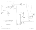
Step Source
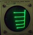
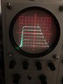
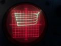
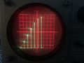
This uses a gated Miller integrator to generate controlled steps. The result is a staircase waveform, which generates different traces in the family of I-V curves of the transistor.
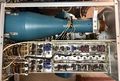
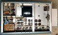
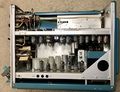
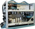
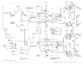
Power Supplies
The 575 contains three separate power supplies:
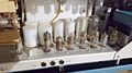
- A main power supply around T601 (120-095 and, later, 120-0095-01), supplying power to the amplifiers and step generator in the 575.
- This power supply follows the standard 500-series power supply design.
- In addition to heater power, it provides −150 V, +100 V, +300 V regulated and +400 V unregulated output.
- It uses a mix of tubes and silicon or selenium rectifiers (earlier S/N) for rectification.
- The −150 V and +400 V unregulated/+300 V regulated rails are supplied through 6BW4 full wave rectifier tubes, the +100 V circuits through silicon diodes/selenium rectifiers.
- The −150 V rail is the main reference supply. Its regulator uses a 5651 voltage reference, a 6AN8 as the comparator/error amplifier, and a 12B4 as series pass tube.
- The +100 V regulator uses a 6080 series pass tube and a 6AU6 tube as the error amplifier.
- The +300 V regulator is similar to the +100 V circuit, except that it uses a 12B4 series pass tube.
- Unregulated +400 V is provided for the CRT HV Oscillator.
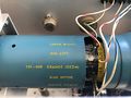
- A high-voltage supply around T801, supplying the CRT voltages, +2300 V for the CRT anode and −1700 V for the CRT cathode.
- This HV power supply uses a 6AQ5 as the HV oscillator tube, and a 12AU7 as the feedback/error amplifier.
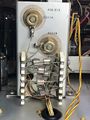
- A collector sweep supply for the device under test.
- Power from the mains goes through an isolation transformer (T701) and a variac (T702) and is rectified by germanium diodes to produce the collector sweep voltage.
- The isolation transformer has two pairs of secondary taps, one for high voltage (0 to 200 V) and low current, the other for low voltage (0 to 20 V) and high current.
- The maximum power that can be delivered to the transistor in either mode is approximately 200 Watts.
- 575s with Mod 122C offer extended collector sweep voltage to 400 V.
Rectifiers
Early 575 versions used selenium rectifiers. A kit for conversion to silicon diodes was available and is documented in the back of the manual.
Type 175 High Current Adaptor

The 575 can be paired with a 175 for high current device measurements.
See Also
Pictures
-

-
NPN Trace
-
575 w/o Mod 122C
-
575 w Mod 122C
-
575 In a Cart
-
Tektronix 575 Mod 118
-
Tektronix 575 Mod 118
-

-
-
Top
-
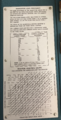
575 Load Resistance Chart
-
-
Rear
-
-
575 Test Panel
-
Test Sockets
-

-
-
575 testing a tunnel diode
-
NPN - Curve of 2N3904
-
PNP - Curve of 2N2207
-
5651 VR Tube in 575
-
hFE curve of a 2N3904 in 575
-
575 with 175


Internal
-
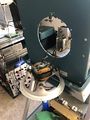
Front without CRT
-
Internal Top
-
Top View without Support Bar
-
Internal Bottom
-
Internal RHS
-

Internal LHS
-

-
-

-
-

-
-
HV Section
-
High-Voltage Power Supply
-
Collector sweep germanium rectifier and dissipation resistor stack
-
Rectifiers - Silicon Diode Version
-
Rear View, Air-filter/Fan Removed.
-
Def Plate Connections
-
-
-
-
Internal Side View
-
Bottom#1
-
Bottom#2
-
Bottom Rear
-
CRT of 575, Type T0520
-
Inside view of a live 575


Schematics
-
Unmodified Collector Supply
-
Collector Supply Rectifier with MOD122C
-
Main Power Supply
-
Step Generator
-
Amplifiers
-
CRT Circuit


Components
Some Parts Used in the 575
| Part | Part Number(s) | Class | Description | Used in |
|---|---|---|---|---|
| 120-0095-01 | 120-0095-01 | Discrete component | power transformer | 575 |
| 120-226 | 120-226 | Discrete component | 117 V/1700 V power transformer | 575 • 560-Series Diode Curve Tracer |
| 12AU6 | 154-0040-00 | Vacuum Tube (Pentode) | RF pentode | 81 • 112 • 1L10 • 1L20 • 1L60 • 3L10 • 512 • 556 • 575 • 545 • 547 • 549 • 581 • 585 • A • B • C • G • K • H • L • ML • M • N • O • R • S • Z |
| 12AU7 | 154-041 • 154-0041-00 • 154-0287-00 | Vacuum Tube (Dual Triode) | dual medium-μ triode | 104 • 104A • 122 • 160 • 161 • 162 • 181 • 190 • 310 • 310A • 316 • 317 • 3C66 • 502 • 502A • 507 • 511A • 512 • 516 • 517 • 517A • 524 • 526 • 535 • 536 • 545 • 545A • 545B • 547 • 549 • 555 • 561 • 564 • 570 • 575 • 581 • 581A • 585 • 585A • C • D • E • N • Q • Hickok 1825 |
| 5642 | 154-0051-00 • 154-0079-00 | Vacuum Tube (Diode) | directly-heated high-voltage rectifier | 310 • 310A • 316 • 317 • 360 • 453 • 502 • 502A • 503 • 504 • 506 • 513 • 515 • 516 • 524 • 529 • RM529 • 533 • 533A • 535 • 536 • 543 • 543A • 543B • 545 • 545A • 545B • 547 • 551 • 555 • 556 • 560 • 561 • 561A • 561S • 564 • 567 • 570 • 575 • 581 • 581A • 585 • 585A • 647 • 647A |
| 6080 | 154-0056-00 • 154-0315-00 | Vacuum Tube (Dual Triode) | dual power triode | 132 • 160 • 316 • 317 • 516 • 535 • 535A • RM35A • 541 • 541A • 535 • 536 • 545 • 545A • 545B • 546 • 547 • 549 • 565 • 567 • 575 • 581 • 581A • 585 • 585A |
| 6AN8 | 154-078 • 154-0078-00 | Vacuum Tube (Triode/Pentode) | triode-pentode combo | 310 • 310A • 316 • 317 • 360 • 502 • 502A • 516 • 517 • 517A • 526 • 565 • 570 • 575 • N |
| 6AQ5 | 154-017 • 154-0017-00 | Vacuum Tube (Pentode) | beam pentode | 310 • 310A • 316 • 360 • 507 • 511A • 512 • 517 • 517A • 524 • 536 • 570 • 575 |
| 6AU6 | 154-0022-00 • 157-0073-00 • 157-0059-00 • 154-0284-00 | Vacuum Tube (Pentode) | RF pentode | 107 • 160 • 181 • 190 • 60 • 2A60 • 72 • 3A72 • 3C66 • 310 • 310A • 316 • 317 • 360 • 502 • 502A • 506 • 511 • 511A • 512 • 513 • 516 • 517 • 517A • 524 • 526 • 529 • RM529 • 531 • 531A • 535 • 536 • 545 • 545A • 546 • 547 • 549 • 555 • 561 • 561A • 561S • 564 • 565 • 567 • 570 • 575 • 581 • 581A • 585 • 585A • 80 • C • CA • Q |
| 6BW4 | 154-0119-00 | Vacuum Tube (Dual Diode) | dual diode | 126 • 502 • 502A • 524 • 575 |
| 6CG7 | 154-0134-00 | Vacuum Tube (Dual Triode) | dual triode | 3C66 • 575 • Q |
| T0520 | 154-0093-00 • 154-0097-00 • 154-0102-00 • 154-0103-00 • 154-0129-00 • 154-0162-00 • 154-0176-00 • 154-0343-00 | CRT | 5" CRT | 525 • 532 • 570 • 575 |