500 Series plug-in interface: Difference between revisions
No edit summary |
No edit summary |
||
| (21 intermediate revisions by 4 users not shown) | |||
| Line 1: | Line 1: | ||
[[File:500 series plugin interface V.png|thumb| | [[File:500 series plugin interface V.png|thumb|200px|right| Plug-in pinout from [[535]] schematic - click to enlarge]] | ||
The '''plug-in interface of the [[500-series scopes]]''' is a single 16-pin Amphenol connector. | The '''plug-in interface of the [[500-series scopes]]''' is a single 16-pin Amphenol connector. | ||
==Pin-out== | ==Pin-out== | ||
{|border="0" | |||
|- valign="top" | |||
| width="350px" | | |||
{| class="wikitable" | {| class="wikitable" | ||
| Line 13: | Line 16: | ||
| 1 || bgcolor="Yellow" | +Signal || 100 mV/cm, bias +67.5 V ±2% | | 1 || bgcolor="Yellow" | +Signal || 100 mV/cm, bias +67.5 V ±2% | ||
|- | |- | ||
| 2 || | | 2 || bgcolor="Pink" | Ground || | ||
|- | |- | ||
| 3 || bgcolor="Yellow" | −Signal || 100 mV/cm, bias +67.5 V ±2% | | 3 || bgcolor="Yellow" | −Signal || 100 mV/cm, bias +67.5 V ±2% | ||
|- | |- | ||
| 4 || bgcolor="Yellow" | Int Trig GND || [[544]], [[546]], [[547]], [[549]], [[556]], late [[555]] only | | 4 || bgcolor="Yellow" | Int Trig GND || [[544]], [[546]], [[547]], [[549]],<br />[[556]], late [[555]] only | ||
|- | |- | ||
| 5 || bgcolor="Yellow" | Int Trig + || [[544]], [[546]], [[547]], [[549]], [[556]], late [[555]] only | | 5 || bgcolor="Yellow" | Int Trig + || [[544]], [[546]], [[547]], [[549]],<br />[[556]], late [[555]] only | ||
|- | |- | ||
| 6 || bgcolor="LightGreen" | Sawtooth || [[556]] only, others n/c | | 6 || bgcolor="LightGreen" | Sawtooth || [[556]] only, others n/c | ||
|- | |- | ||
| 7 || bgcolor="LightGreen" | Slave Pulse out || [[547]] only | | 7 || bgcolor="LightGreen" | Slave Pulse out || [[547]] only | ||
|- | |- | ||
| 8 || bgcolor="LightGreen" | Multi-trace sync || Cathode; grounded by [[CA]], [[M]] etc. in Alt Trace mode | | 8 || bgcolor="LightGreen" | Multi-trace sync || Cathode; grounded by [[CA]],<br />[[M]] etc. in Alt Trace mode | ||
|- | |- | ||
| 9 || bgcolor="Pink" | −150 V || min. 3.8 mA, max. 60 mA | | 9 || bgcolor="Pink" | −150 V || min. 3.8 mA, max. 60 mA | ||
| Line 35: | Line 38: | ||
| 12 || bgcolor="Pink" | +350 V || min. 0 mA, max. 20 mA | | 12 || bgcolor="Pink" | +350 V || min. 0 mA, max. 20 mA | ||
|- | |- | ||
| 13 || bgcolor="LightBlue" | 6.3 V<sub>AC</sub> || plug-in AC heater supply, max. 2.8 A | | 13 || bgcolor="LightBlue" | 6.3 V<sub>AC</sub> || plug-in AC heater supply,<br />max. 2.8 A | ||
|- | |- | ||
| 14 || bgcolor="LightBlue" | 6.3 V<sub>AC</sub> || return for pin 13 | | 14 || bgcolor="LightBlue" | 6.3 V<sub>AC</sub> || return for pin 13 | ||
|- | |- | ||
| 15 || bgcolor="Pink" | +75 V || min./max. 150 mA for DC series heaters and LV supply | | 15 || bgcolor="Pink" | +75 V || min./max. 150 mA for DC<br />series heaters and LV supply | ||
|- | |- | ||
| 16 || bgcolor="LightGreen" | Multi-trace sync || Anode | | 16 || bgcolor="LightGreen" | Multi-trace sync || Anode | ||
|} | |} | ||
| Line 48: | Line 50: | ||
:{| | :{| | ||
|- | |- | ||
| bgcolor="Pink" | DC | | bgcolor="Pink" | DC power and ground | ||
|- | |- | ||
| bgcolor="LightBlue" | AC and heater power | | bgcolor="LightBlue" | AC and heater power | ||
| Line 55: | Line 57: | ||
|- | |- | ||
| bgcolor="LightGreen" | Control Signals | | bgcolor="LightGreen" | Control Signals | ||
|} | |||
| | |||
==Signal Input Impedance and Spoiler Switch Hole== | |||
The input impedance of 500-series scopes presented to the plug-in at pins 1+3 is approximately kept constant by adding shunt capacitors at the input depending on the tube type used. Early, scopes like the [[536]] and the [[555]] use a [[12BY7]] differential amplifier in the input stage, and the plug-in is loaded with the grid input capacitance with 2x 27 Ω (555) or 47 Ω (536) in series. Later, medium speed scopes like the [[545B]] and the [[549]] use dual input followers with a [[6DJ8]] tubes and 2x 47 Ω in series at the grids, so to keep the plug-in loading approximately constant a 3.9 pF capacitor is placed across pins 1 and 3 in the scope. | |||
High-speed scopes designed for 1-series plug-ins and up to 50 MHz bandwidth use a even lower input capacitance dual follower implemented with [[12AT7|12AT7s]] and series grid resistors of 22 Ω. For compatibility with older plugins designed for a higher capacitive load a series network of 7.5 pF and 82 Ω is shunted accross pins 1 and 3 by means of a switch. This spoiler switch is activated by all slower letter plugins. High speed plugins like the [[1A1]] have a hole in the back plate to allow for the switch plunger to pass through and access the full system bandwidth of the scope. Scopes and adapters known to use this spoiler switch are the [[544]], [[546]], [[547]], [[556]], and the [[81A]]. | |||
* [[Media:Spoiler switch rationale from Tek 547 544 546 tech instr and training.pdf|Spoiler switch explanation excerpted from Tek 547 544 546 Technical Instruction and Training (PDF)]] | |||
* [[Media:Spoiler switch rationale from Tek 547 notes.pdf|Spoiler switch explanation excerpted from Tek 547 Notes (PDF)]] | |||
==Internal Trigger signal== | |||
In early 500-series systems (e.g., a [[C|Type C plug-in]] in a [[535|535 mainframe]]), | |||
the mainframe's triggering is based on the main vertical signal (pins 1/3). | |||
In these scopes, changing the vertical position control on the plug-in | |||
interacts with the trigger level setting if the scope is set to a DC trigger mode. | |||
In somewhat later 500-series systems (e.g. [[547|Type 547]]), the plug-in (e.g. [[1A1|Type 1A1]]) | |||
provides the mainframe with a separate trigger signal on pin 5 whose DC level is not affected by | |||
the vertical position knob. In multi-trace setups, this allows consistent triggering from a specific | |||
input channel independent of which channel is currently being drawn on CRT. | |||
For backward compatibility, the 547-era scopes have two types of INT triggering, taking the trigger | |||
signal either from the main vertical plug-in output (1/3), or the trigger output (5). | |||
Although the Type 1A1 has two input channels, they are not identical - the pin 5 internal trigger | |||
signal is always taken from channel 1. Even later 500-series plug-ins (e.g., the [[1A4|Type 1A4]]), | |||
have a knob for the selection of which input channel's signal supplies the trigger signal. | |||
|} | |} | ||
==Pictures == | |||
<gallery> | <gallery> | ||
Pluginpinout556.png | pinout shown in 556 schematic | Pluginpinout556.png | pinout shown in [[556]] schematic | ||
040-0065-00 p4.jpg | pinout listed in 040-0065-00 kit docs | 040-0065-00 p4.jpg | pinout listed in [[040-0065-00]] kit docs | ||
Tek letter-series pinout.png | pinout shown in 1A2 schematic | Tek letter-series pinout.png | pinout shown in [[1A2]] schematic | ||
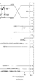
544_vertical_amp_input.GIF | [[544]] vertical amplifier input with spoiler switch SW1000 | |||
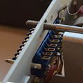
500-series connector male front.jpg| Male pins on plugin | 500-series connector male front.jpg| Male pins on plugin | ||
500-series connector male rear.jpg | Rear lugs on plugin | 500-series connector male rear.jpg | Rear lugs on plugin | ||
Tek_k_1498_6.jpg | Back plate of [[K]] plug-in without spoiler hole | |||
Late_tek_type_j_rear.jpg | Back plate of [[1A1]] plug-in with spoiler hole (circular hole right of 16-pin Amphenol connector) | |||
</gallery> | </gallery> | ||
[[Category:Plug-in interfaces]] | [[Category:Plug-in interfaces]] | ||
Latest revision as of 10:35, 8 August 2021

The plug-in interface of the 500-series scopes is a single 16-pin Amphenol connector.
Pin-out
Pin group function legend
|
Signal Input Impedance and Spoiler Switch HoleThe input impedance of 500-series scopes presented to the plug-in at pins 1+3 is approximately kept constant by adding shunt capacitors at the input depending on the tube type used. Early, scopes like the 536 and the 555 use a 12BY7 differential amplifier in the input stage, and the plug-in is loaded with the grid input capacitance with 2x 27 Ω (555) or 47 Ω (536) in series. Later, medium speed scopes like the 545B and the 549 use dual input followers with a 6DJ8 tubes and 2x 47 Ω in series at the grids, so to keep the plug-in loading approximately constant a 3.9 pF capacitor is placed across pins 1 and 3 in the scope. High-speed scopes designed for 1-series plug-ins and up to 50 MHz bandwidth use a even lower input capacitance dual follower implemented with 12AT7s and series grid resistors of 22 Ω. For compatibility with older plugins designed for a higher capacitive load a series network of 7.5 pF and 82 Ω is shunted accross pins 1 and 3 by means of a switch. This spoiler switch is activated by all slower letter plugins. High speed plugins like the 1A1 have a hole in the back plate to allow for the switch plunger to pass through and access the full system bandwidth of the scope. Scopes and adapters known to use this spoiler switch are the 544, 546, 547, 556, and the 81A.
Internal Trigger signalIn early 500-series systems (e.g., a Type C plug-in in a 535 mainframe), the mainframe's triggering is based on the main vertical signal (pins 1/3). In these scopes, changing the vertical position control on the plug-in interacts with the trigger level setting if the scope is set to a DC trigger mode. In somewhat later 500-series systems (e.g. Type 547), the plug-in (e.g. Type 1A1) provides the mainframe with a separate trigger signal on pin 5 whose DC level is not affected by the vertical position knob. In multi-trace setups, this allows consistent triggering from a specific input channel independent of which channel is currently being drawn on CRT. For backward compatibility, the 547-era scopes have two types of INT triggering, taking the trigger signal either from the main vertical plug-in output (1/3), or the trigger output (5). Although the Type 1A1 has two input channels, they are not identical - the pin 5 internal trigger signal is always taken from channel 1. Even later 500-series plug-ins (e.g., the Type 1A4), have a knob for the selection of which input channel's signal supplies the trigger signal. |
Pictures
-
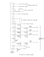
pinout shown in 556 schematic
-
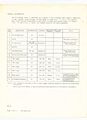
pinout listed in 040-0065-00 kit docs
-
pinout shown in 1A2 schematic
-

544 vertical amplifier input with spoiler switch SW1000
-
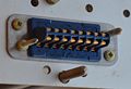
Male pins on plugin
-
Rear lugs on plugin
-
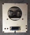
Back plate of K plug-in without spoiler hole
-
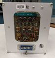
Back plate of 1A1 plug-in with spoiler hole (circular hole right of 16-pin Amphenol connector)


