3S6: Difference between revisions
Jump to navigation
Jump to search
No edit summary |
No edit summary |
||
| (2 intermediate revisions by 2 users not shown) | |||
| Line 9: | Line 9: | ||
|discontinued=(?) | |discontinued=(?) | ||
|manuals= | |manuals= | ||
* [[Media:070-0789-00.pdf|Tektronix 3S6 Manual]] | * [[Media:070-0789-00.pdf|Tektronix 3S6 Manual]] (OCR) | ||
}} | }} | ||
The '''Tektronix 3S6''' is a dual-trace [[sampling oscilloscope|sampling]] module for [[560-series scopes]], particularly the [[568]]. | The '''Tektronix 3S6''' is a dual-trace [[sampling oscilloscope|sampling]] module for [[560-series scopes]], particularly the [[568]]. | ||
It interfaces with the sampling heads through a connector on its rear panel (using [[S-series sampling head extenders]]). | It interfaces with the sampling heads through a connector on its rear panel (using [[S-series sampling head extenders]]). | ||
Deflection factor, DC offset and polarity, as well as normal/smooth mode can be programmed externally from a controller such as the [[240]] / [[241|241 Programmer]]. | |||
The [[067-0584-99|067-0584-99 Remote Programmer calibration fixture]] is available to do this manually during setup/calibration. | |||
In a typical setup, the programming unit is connected to the 568 using a multi-conductor cable. | In a typical setup, the programming unit is connected to the 568 using a multi-conductor cable. | ||
| Line 26: | Line 23: | ||
==Links== | ==Links== | ||
{{Documents|Link=3S6}} | |||
{{PatentLinks|3S6}} | |||
==Pictures== | ==Pictures== | ||
Latest revision as of 11:00, 19 June 2024

The Tektronix 3S6 is a dual-trace sampling module for 560-series scopes, particularly the 568.
It interfaces with the sampling heads through a connector on its rear panel (using S-series sampling head extenders). Deflection factor, DC offset and polarity, as well as normal/smooth mode can be programmed externally from a controller such as the 240 / 241 Programmer. The 067-0584-99 Remote Programmer calibration fixture is available to do this manually during setup/calibration.
In a typical setup, the programming unit is connected to the 568 using a multi-conductor cable. The 568 routes those signals to the plug-ins.
Key Specifications
- please add
Links
Documents Referencing 3S6
| Document | Class | Title | Authors | Year | Links |
|---|---|---|---|---|---|
| Service Scope 53 Dec 1968.pdf | Article | Digital Systems Come Of Age | John Bowne | 1968 | 3T5 • 3T6 • 3S5 • 3S6 • S-1 • S-2 • S-3 • S-4 • 568 • 230 |
| Service scope dec 1968 ocr.pdf | Article | Digital Systems Come of Age | John Bowne | 1968 | 3T5 • 3T6 • 3S5 • 3S6 • S-1 • S-2 • S-3 • S-4 • 568 • 230 • 240 • 241 • 250 |
| Service Scope 52 Oct 1968.pdf | Article | The State of the Art in Sampling | Al Zimmerman | 1968 | S-1 • S-2 • S-3 • S-4 • S-50 • S-51 • 285 • 3S1 • 3S2 • 3S5 • 3S6 • 3T2 • 3T5 • 3T6 • 3T77A • 568 • 230 |
| Tekscope 1971 V3 N5 Sep 1971.pdf | Article | The R1340 Data Coupler | 1971 | R1340 • 568 • 3S6 • 3T6 |
Pictures
-
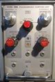
Front
-
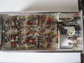
Left
-
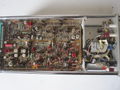
Right
-
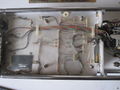
Connector to PCB


