7503: Difference between revisions
No edit summary |
No edit summary |
||
| Line 5: | Line 5: | ||
introduced=1970 | | introduced=1970 | | ||
discontinued=1972 | | discontinued=1972 | | ||
summary= | summary=90 MHz non-storage mainframe| | ||
manuals= | manuals= | ||
* [ | * [[Media:070-1039-00.pdf|7503 Instruction Manual]] (partial, PDF) | ||
* ''please add complete manual and/or schematics'' [[Category:Manual needed]] | |||
}} | }} | ||
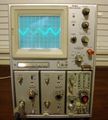
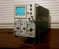
The '''Tektronix 7503''' is a | The '''Tektronix 7503''' is a 90 MHz 7000-series mainframe with three module bays, [[introduced in 1970]]. It was effectively replaced by the larger-screen [[7603]] in 1972. | ||
The 7503 project was managed by [[Phil Crosby]], and was supposed to be a [[7504]] but with one fewer plug-in. | The 7503 project was managed by [[Phil Crosby]], and was supposed to be a [[7504]] but with one fewer plug-in. | ||
| Line 22: | Line 21: | ||
==Specifications== | ==Specifications== | ||
[[ | {{BeginSpecs}} | ||
{{Spec | Bandwidth | 90 MHz with [[7A11]], [[7A16]] (and faster plug-ins); 75 MHz with [[7A12]], [[7A13]], [[7A14]] }} | |||
{{Spec | Fastest calibrated sweep | 5 ns/Div }} | |||
{{Spec | CRT | [[154-0608-00|154-0608-xx]] }} | |||
{{Spec | Vertical modes | Left / Alt / Add / Chop / Right }} | |||
{{Spec | Trigger Source | Left / Vert Mode / Right }} | |||
{{Spec | Calibrator | 4 mV to 40 V in five decade steps, 40 mA, 1 kHz ±0.5% }} | |||
{{Spec | Outputs | Side panel: Vert signal, +Gate, +Sawtooth; At CRT: Camera power }} | |||
{{Spec | Line Voltage | 90-110 V / 104-126 V / 112-136 V / 180-220 V / 208-252 V / 224-272 V, 50—440 Hz }} | |||
{{Spec | Power | Max. 258 W }} | |||
{{Spec | Weight | 21.3 kg / 47 lb (instrument only) }} | |||
{{Spec | Rear connectors | | |||
* High speed Z Axis input (BNC connector, 60 V<sub>p-p</sub>, 75 MHz) | |||
* High sensitivity Z Axis input (BNC connector, 2 V<sub>p-p</sub>, 10 MHz) | |||
* Two [[LEMO S-series connector]]s for [[probe power]] | |||
* [[Amphenol 165 series connectors|Amphenol 165-16 connector]] (J1075) for [[7503, 7504, 7904 remote control connector|remote control]] (single sweep ready/reset signals) | |||
}} | |||
{{EndSpecs}} | |||
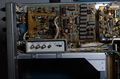
==Internals== | |||
Like other 75xx and 76xx mainframes and the 7504, the 7503 has a linear power supply, as opposed to the switchmode supplies used in the later 4-slot mainframes. | |||
==Pictures== | ==Pictures== | ||
<gallery> | <gallery> | ||
Tek 7503 front.JPG|Front | Tek 7503 front.JPG|Front | ||
Revision as of 06:54, 24 January 2021

The Tektronix 7503 is a 90 MHz 7000-series mainframe with three module bays, introduced in 1970. It was effectively replaced by the larger-screen 7603 in 1972.
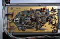
The 7503 project was managed by Phil Crosby, and was supposed to be a 7504 but with one fewer plug-in. The 7503 was Tek's first scope to use a harmonica connector for inter-board wiring. Prior to this, inter-board wiring had either mainly been point-to-point soldered. Other approaches were taken on certain instruments, for example the 7704, in which pins sticking out of the chassis mate with holes in the boards that receive the pins and make electrical contact.
Specifications
Key Specifications
| Bandwidth | 90 MHz with 7A11, 7A16 (and faster plug-ins); 75 MHz with 7A12, 7A13, 7A14 |
|---|---|
| Fastest calibrated sweep | 5 ns/Div |
| CRT | 154-0608-xx |
| Vertical modes | Left / Alt / Add / Chop / Right |
| Trigger Source | Left / Vert Mode / Right |
| Calibrator | 4 mV to 40 V in five decade steps, 40 mA, 1 kHz ±0.5% |
| Outputs | Side panel: Vert signal, +Gate, +Sawtooth; At CRT: Camera power |
| Line Voltage | 90-110 V / 104-126 V / 112-136 V / 180-220 V / 208-252 V / 224-272 V, 50—440 Hz |
| Power | Max. 258 W |
| Weight | 21.3 kg / 47 lb (instrument only) |
| Rear connectors |
|
Internals
Like other 75xx and 76xx mainframes and the 7504, the 7503 has a linear power supply, as opposed to the switchmode supplies used in the later 4-slot mainframes.
Pictures
-
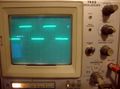
Front
-
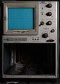
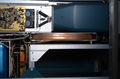
Plug-in bay
-

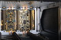
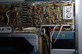
Plug-in connectors missing sides
-
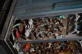
Horizontal amp on top
-
Vertical amp on the side
-
Left view, delay cable, CRT
-
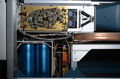
Left view, power supply
-
Right view, mains frequency transformer
-
Readout board
-
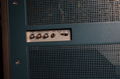
Right side connector panel
-

Rear
-
-
-