7A12

The Tektronix 7A12 is a 120 MHz dual-trace vertical plug-in for 7000-series scopes. This original 7000-series plugin allows large dc offset voltages, however the offset voltage is not available on the front panel to be measured externally as with the 7A11.
Switches on the front panel control miniature relays in the signal path to select input attenuators, through logic circuits.
The 7A12 was designed by Roy Hayes (who also designed the 3A3 and 3A8 before leaving for HP Loveland in Jan 1971). The Evaluation Engineer for the 7A12 was Peter Starič, co-author of the book "Wideband Amplifiers" with Erik Margan. Peter and his daughter, Zorana, returned to Ljubljana on August 4, 1970.
Key Specifications
| Bandwidth | 120 MHz (79xx) / 105 MHz (77xx) / 55 MHz (74xx) |
|---|---|
| Deflection | 5 mV/Div to 5 V/Div (1–2–5), variable up to 12.5 V/Div |
| Input impedance | 1 MΩ // 24 pF |
| Timing | Delay difference between channels < 500 ps |
| Channel isolation | At least 3000:1 at 75 MHz |
| Maximum input | 350 V DC + Peak AC at 1 kHz or less |
| DC offset | At least ±500 divisions |
Internals
The 7A12 uses the 155-0032-00 custom IC as a gain stage and the 155-0022-00 for channel switching.
John Addis writes: "There were two mistakes, conceptual errors, that doomed the 7A12 from 'day one'. The first was in deciding to use the 1 GHz FT Tektronix IC process (called 50/450 for resistivities of the two base layers) for the signal path. This process was Tektronix' fastest but too slow for a plugin expected to provide 150 MHz bandwidth in the fastest original mainframe, the 7704. At the same time, HP had a 2.5 GHz process used in the 1830A, 250MHz, dual channel 50 ohm only plugin.
"The second 'day one' mistake, later pointed out by Tom Rousseau, was to arrange the two channels side by side. Roy wanted to be able to go from one sensitivity (deflection factor) to another without having to go through all the sensitivities in between as happens with a rotary switch. The vertical row of push buttons was functionally attractive. However, that would require both channels to occupy the same space if on a single, centered, vertical circuit board.
"The solution was two separate, mirror image attenuator (V/Div) boards, and two mirror image push button V/division selection boards. There was the essential Main center board which connects signal and power to a socket in the mainframe. There were also two identical amplifier boards that took clever advantage of an asymmetrical output. To make matters worse, the two attenuator boards were made with PPO (polyphenylene oxide), an expensive low dielectric constant material to keep the input capacitance low. There were 11 circuit boards, nine of them unique. All of this was obviously extremely expensive.
"As part of the 7403 program to bring a low cost entry product into the 7K series of plugins, Tom Rousseau was assigned to design a new dual trace plugin. Realizing the 7A12's problems, Tom put one channel physically above the other. Almost all of this was done on a single circuit board. The plugin had only 80 MHz bandwidth but was much less expensive to manufacture. The design was classical, had none of the complicated offset circuitry, and the channel switch was the same venerable 155-0022-00 used in the 7A12. The expensive PPO circuit board material was still necessary, but Tom used a cam switch, less expensive than Tek relays to select the deflection factor (sensitivity). It became the 7A18."
Tom Rousseau writes: "After the 7A18 project, and becoming familiar with the M84 (155-0078-xx) IC, I conjured up the 7A26 concept based on the general layout of the 7A18. I figured that with the M84, I could more than double the bandwidth of the 7A18 and provide a reasonably higher bandwidth, 1 megohm dual trace plug-in. Furthermore, I offered the possibility of making four vertical plug-ins from one basic design: 7A26, 7A24 (50 ohm), 7A16A (1 megohm, single channel) and a fourth not pursued, 7Axx, single channel, 50 Ohm. I worked on this for awhile then popped the idea to management (Oliver Dalton), who agreed to three of the plug-ins."
The 7A26 became the best selling Tektronix plugin of all time. Tektronix literally gold plated a 7A26 and gave it to Tom in recognition.
See https://vintagetek.org/100000-7a26-plug-in/
Links
Documents Referencing 7A12
| Document | Class | Title | Authors | Year | Links |
|---|---|---|---|---|---|
| Tekscope 1969 V1 N5 Oct 1969.pdf | Article | Introducing the New Generation | 1969 | 7000-series scopes • 7504 • 7704 • 7A11 • 7A12 • 7A13 • 7A14 • 7A16 • 7A22 • 7S11 • 7M11 • 7B50 • 7B51 • 7B70 • 7B71 • 7T11 • R5030 • 7000 series readout system • Miniature relays • Cam switches • Industrial Design • T7500 • T7700 • P6052 • P6053 • C-50 • C-51 • 204-2 | |
| Tekscope 1969 V1 N6 Dec 1969.pdf | Article | A New Logic for Oscilloscope Displays | 1969 | 7000-series scopes • 7A11 • 7A12 • 7A13 • 7A14 • 7A16 • 7A22 • 7B50 • 7B51 • 7B70 • 7B71 • 7S11 • 7T11 • 7504 • 7704 | |
| 7000 series brochure March 1973.pdf | Brochure | 7000 series brochure, March 1973 | 1973 | 7A11 • 7A12 • 7A13 • 7A14 • 7A15A • 7A16A • 7A17 • 7A18 • 7A19 • 7A21N • 7A22 • 7B50 • 7B53A • 7B70 • 7B71 • 7B92 • 7CT1N • 7D11 • 7D13 • 7D14 • 7D15 • 7M11 • 7L12 • 7S11 • 7S12 • 7T11 • 7704A • R7704 • 7904 • R7903 • 7603 • R7603 • 7403N • R7403N • 7313 • R7313 • 7613 • R7613 • 7623 • R7623 • P7001 |
Pictures
-
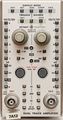
Front view
-
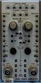
Front view
-
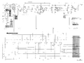
Attenuator schematic with relays
-
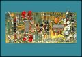
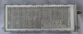
7A12 Amplifier PCB
-
Left side view


Components
Some Parts Used in the 7A12
| Part | Part Number(s) | Class | Description | Used in |
|---|---|---|---|---|
| 148-0034-01 | 148-0034-01 | Discrete component | miniature DPDT relay | 485 • 7A12 |
| 148-0034-02 | 148-0034-02 | Discrete component | miniature DPDT relay | 7A12 |
| 155-0022-00 | 155-0022-00 • 155-0022-01 | Monolithic integrated circuit | analog multiplexer | 147 • 148 • 149 • 335 • 468 • 1430 • 1441 • 1461 • 1900 • 1910 • 2220 • 2221 • 2230 • 5223 • 5403 • 5440 • 5441 • 5443 • 5444 • 5A38 • 7313 • 7403N • 7503 • 7504 • 7514 • 7603 • AN/USM-281C • 7613 • 7623 • 7623A • 7633 • 7704 • R7704 • 7704A • 7834 • 7844 • 7854 • R7912 • 7912AD • 7912HB • 7904 • R7903 • 7904A • 7934 • 7A12 • 7A18 • 7A18A • 7A18N • 7B52 • 7B53N • 7D10 • 7D11 • 7D12 • NT-7000 • P7001 |
| 155-0032-00 | 155-0032-00 • 155-0032-01 | Monolithic integrated circuit | variable-gain transconductance amplifier (voltage in, current out) | 335 • 464 • 465 • 465B • 466 • 475 • 475A • 475M • 634 • 650 • 651 • 652 • 653 • 655 • 656 • 670 • 671 • 7A12 • 475 • FG504 • 1440 • 1460 • 1480 • 1481 • 1482 • 1485 |