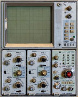
7603: Difference between revisions
No edit summary |
(+pic) |
||
| Line 113: | Line 113: | ||
File:Tek-7603-back-open.jpg | Rear view with LV regulator board flipped out | File:Tek-7603-back-open.jpg | Rear view with LV regulator board flipped out | ||
File:Tek-7603-lvreg.jpg | low voltage regulator board | File:Tek-7603-lvreg.jpg | low voltage regulator board | ||
File:Tek-7603-bottom.jpg | Bottom view of backplane. Backplane interconnect board is seen in center, vertical interface and | File:Tek-7603-bottom.jpg | Bottom view of backplane. Backplane interconnect board is seen in center, vertical interface and trigger selector piggyback boards on left/top left, logic board on right. | ||
File:Tek-7603-logic-board.jpg | Logic board (normally situated on back of main interconnect facing the PSU) | File:Tek-7603-logic-board.jpg | Logic board (normally situated on back of main interconnect facing the PSU) | ||
File:Tek-7603-vertif-trigselect.jpg | Trig Select and Vertical Interface boards | File:Tek-7603-vertif-trigselect.jpg | Trig Select and Vertical Interface boards | ||
File:Tek-7603-interconnect.jpg | Backplane interconnect without Vertical Interface and Trigger Selector piggyback boards | |||
</gallery> | </gallery> | ||
Revision as of 10:54, 2 June 2015
The Tektronix 7603 is a general-purpose 100 MHz non-storage, large screen scope that takes
two 7000-series vertical plug-ins
and one 7000-series horizontal plug-in.
The AN/USM 281C is a ruggedized 7603 without readout (was also known as 7603N Option 11S) that includes two AM-6565 (7A15AN11) single-trace amplifiers, a TD-1085 (7B53AN11) dual time base, and a clip-on front panel cover with probes and accessories.
Key Specifications
| Bandwidth | 100 MHz with 7A11, 7A16, 7A17; 110 MHz with 7A19, 70 MHz with 7A18 |
|---|---|
| Fastest calibrated sweep | 5 ns/Div |
| CRT std. | P31 phosphor, 8 × 10 divisions of 1.22 cm (Tek T7400/154-0640-00 tube); 15 kV acceleration (-3/+12); Option 8: P11 phosphor |
| CRT Opt. 4 | P31 phosphor, 8 × 10 divisions of 1.0 cm (Tek 154-0672-00 tube); 18 kV acceleration |
| CRT Opt. 6 | P31 phosphor, 8 × 10 divisions of 1.22 cm (Tek 154-0673-00 tube, spectrum analyzer graticule) |
| Vertical modes | Left / Alt / Add / Chop / Right |
| Trigger Source | Left / Vert Mode / Right |
| Inputs | Z Axis |
| Outputs | Camera power, Vert signal, +Gate, +Sawtooth |
| Line Voltage | 100 / 110 / 120 / 200 / 220 / 240 V, +/- 10%, 50—440 Hz |
| Power | Max. 170 W |
| Weight | 13.6 kg / 30 lb (instrument only) |
| Operating Environment | 0°C – +50°C, < 15,000 ft |
Options
- Opt.1: Without readout (= 7603N)
- Opt.3: Extra EMI shielding
- Opt.4/Opt.13: Maximum-brightness CRT with reduced area
- Opt.5: Fan
- Opt.6: Spectrum analyzer graticule
- Opt.7: Without Signals Out
- Opt.8: P11 phosphor
- Opt.11S: Ruggedized variant AN/USM 281C, specified at 50 MHz
Internals
The 7603 was made in various versions for many years, with revisions to some subassemblies like the vertical output amplifier and HV circuits. It uses a linear power supply, a fan is optional. CRT deflection plates are not distributed. The vertical output amplifier is built around a 155-0080-00 hybrid. Other custom Tek ICs used include 155-0011-00 clock & chop blanking, 155-0022-00 channel switch, and the 7000 series readout system chips.
Prices
| Year | 1973 | 1976 | 1980 | 1984 | 1990 | |
|---|---|---|---|---|---|---|
| Mainframe only | Catalog price | $1,600 | $1,800 | $2,260 | $2,865 | $4,235 |
| 2015 value | $8,500 | $7,470 | $6,480 | $6,510 | $7,650 | |
| Mainframe with 2 × 7A18 + 7B53 | Catalog price | $3,520 | $3,955 | $5,225 | $6,880 | $10,315 |
| 2015 value | $18,720 | $16,410 | $14,970 | $15,640 | $18,630 |
Links
- Detailed repair report @ amplifier.cd (German) / (translated)
- Tek 7603 @ barrytech.com
- Catalog page with specs
- Repair Report #2
- Repair Report #3
- Repair Report #4 - 7603 with 7D20
- No plug-in lights on the 7603 Mainframe
- EB5AGV's Tektronix R7603 / 7D20 page
- Picture of a completely disassembled 7603
Pictures
-
Tektronix 7603, front view
-
R7603
-
7603, left side - center left: vertical amplifier
-
7603, right side - left: calibrator, center left: readout, center right: cover of HV board
-
7603, top view - top: Z axis board, bottom: horizontal amplifier board
-
Interior view of rear panel showing part of LV regulator board
-
Rear view with LV regulator board flipped out
-
low voltage regulator board
-
Bottom view of backplane. Backplane interconnect board is seen in center, vertical interface and trigger selector piggyback boards on left/top left, logic board on right.
-
Logic board (normally situated on back of main interconnect facing the PSU)
-
Trig Select and Vertical Interface boards
-
Backplane interconnect without Vertical Interface and Trigger Selector piggyback boards


