7D01: Difference between revisions
No edit summary |
No edit summary |
||
| Line 15: | Line 15: | ||
<small> | <small> | ||
'''Alternate copies''' | '''Alternate copies''' | ||
* [https://w140.com/smb/7d01_sm.pdf 7D01 Instruction Manual, revised Oct 1982, part no 070-2206-02 (OCR | * [https://w140.com/smb/7d01_sm.pdf 7D01 Instruction Manual, revised Oct 1982, part no 070-2206-02] (OCR) | ||
'''Brochures''' | '''Brochures''' | ||
* [[Media:Logic Analyzers Brochure 1976.pdf|Tektronix Logic Analyzers Brochure 1976 | * [[Media:Logic Analyzers Brochure 1976.pdf|Tektronix Logic Analyzers Brochure 1976]] | ||
</small> | </small> | ||
}} | }} | ||
| Line 27: | Line 27: | ||
The 9<sup>th</sup> channel on the first probe serves as an external clock input, that on the second probe as an external qualifier . | The 9<sup>th</sup> channel on the first probe serves as an external clock input, that on the second probe as an external qualifier . | ||
The input logic threshold can be set to 1.4 V for TTL, a screwdriver-adjustable voltage (VAR) between −12 V and +12 V, or a mixed mode (TTL-VAR) where the first probe (0–7, CLK) is set to | The input logic threshold can be set to 1.4 V for TTL, a screwdriver-adjustable voltage (VAR) between −12 V and +12 V, or a mixed mode (TTL-VAR) where the first probe (0–7, CLK) is set to the variable voltage, and the second probe (9−15, QUAL) to 1.4 V. | ||
The 7D01 acquires data asynchronously using an internal clock from 10 ns to 50 ms per sample, or synchronously based on an external clock. | The 7D01 acquires data asynchronously using an internal clock from 10 ns to 50 ms per sample, or synchronously based on an external clock. | ||
Revision as of 10:47, 13 December 2021

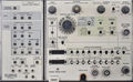
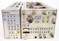
The Tektronix 7D01 is a 16-channel logic analyzer plug-in for the 7000-series scopes that takes two P6451 8+1 channel probes.
When used by itself, it only displays a timing diagram that can be positioned and zoomed using analog controls, and uses the mainframe's readout system to indicate the cursor position (on top) and the binary data pattern at the cursor location (using the two bottom readout fields).
When combined with an optional DF1 or DF2 display formatter (attached to the left of the 7D01 through a DD-50 connector), data domain displays (state table and map) become available.
The 9th channel on the first probe serves as an external clock input, that on the second probe as an external qualifier . The input logic threshold can be set to 1.4 V for TTL, a screwdriver-adjustable voltage (VAR) between −12 V and +12 V, or a mixed mode (TTL-VAR) where the first probe (0–7, CLK) is set to the variable voltage, and the second probe (9−15, QUAL) to 1.4 V.
The 7D01 acquires data asynchronously using an internal clock from 10 ns to 50 ms per sample, or synchronously based on an external clock. A built-in word recognizer can trigger on any combination of the 16 data signals, plus the probe and external qualifier inputs. The recognizer's output is available to trigger an external unit, e.g. when the 7D01 is combined with amplifier and timebase plug-ins in a 4-bay mainframe.
The 7D01 is also compatible with the DL2 or DL502 latch (glitch detector) that plugs in between the P6451 probes and the 7D01's inputs, and receives the sample clock from the 7D01's Store Clock output.
Project manager for the 7D01 was Murlan Kaufman.
Key Specifications
| Channels |
|
|---|---|
| Sampling Rate | 10 ns to 5 ms per sample (1–2–5) or external clock up to 50 MHz |
| Trigger Sources |
|
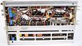
Internals
The 7D01 does not contain a microprocessor and is built entirely from off-the-shelf ECL and TTL logic ICs. The data path, acquisition memory, and clock generator in the 7D01 are built using ECL circuits.
The –4.8 V and –2 V ECL supplies are generated by a 555-driven switcher powered off the ±15 V rails.
There is an internal DB-25 data output connector and a front-panel cut-out for the corresponding cable. (Any known uses?)
Notes
Note about external clock rates (from Jim Mauck):
When I was a Tek Service Technician I worked on the 7D01. For several years I tested every 7D01 I worked on (and that was a lot of them) with a 100 MHz external clock in 16 channel mode. I would use a DF2 and set it to reacquire continuously as long as the 7D01 memory was the same as the original data I stored into the DF2 memory. The analyzer would run for hours without error. The funny part is that it wasn't until I had been doing this for several years that I realized it wasn't specified to run at that frequency. I continued to test them that way even after I discovered my error. However the instrument exceeding the specifications might be due to the data source providing a generous setup and hold time relative to the active clock edge.
Links
Pictures
-
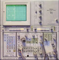
7D01 in 7704A mainframe
-
-
-
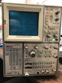
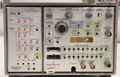
7D01+DF1 Front
-
7D01+DF1 Front
-
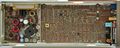
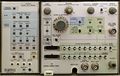
7D01 Left
-
7D01 Right
-

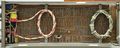
7D01 Bottom
-
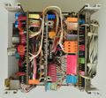
7D01 Rear (back plate removed)
-
-

-
-
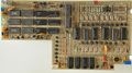
7D01 Cursor Board
-
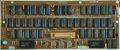
7D01 Memory Board
-
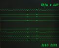
7D01 Timing Diagram
-
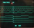
7D01 + DF1 Timing Diagram
-
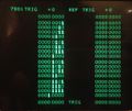
7D01 + DF1 State Table


Custom ICs used in the 7D01
| Page | Model | Part nos | Description | Designers | Used in |
|---|---|---|---|---|---|
| 155-0090-00 | M059 | 155-0090-00 • 155-0090-01 • 155-0090-02 | four-decade counter, latch and D/A converter | Mike Metcalf | 7B85 • 7D01 • 7D12 • 7D15 • 7J20 |
| 155-0171-00 | M150A | 155-0171-00 | four-decade counter, latch and D/A converter | Mike Metcalf | 7B85 • 7D01 • 7D12 • 7D15 • 7J20 |