1L40: Difference between revisions
m (Text replacement - "Category:Spectrum Analyzers" to "Category:Spectrum analyzers") |
No edit summary |
||
| (6 intermediate revisions by 2 users not shown) | |||
| Line 1: | Line 1: | ||
{{Plugin Sidebar | {{Plugin Sidebar | ||
|manufacturer=Tektronix | |||
summary=40 GHz Spectrum Analyzer plug-in | | |series=500-series scopes | ||
image=Tek 1l40 | |type=1L40 | ||
caption=1L40 front | |summary=40 GHz Spectrum Analyzer plug-in | ||
|image=Tek 1l40 front2.jpeg | |||
introduced=1969 | | |caption=1L40 front | ||
discontinued=1972 | | |introduced=1969 | ||
manuals= | |discontinued=1972 | ||
* [ | |manuals= | ||
* [[Media:070-0904-00.pdf|Tektronix 1L40 Manual]] (bad-OCR) | |||
<!-- [http://w140.com/tek_1l40.pdf Tektronix 1L40 Manual]] (bad scan)--> | |||
* [[Media:Tek 1l40 fcp march 1969.pdf|Tektronix 1L40 Factory Calibration Procedure, March 1969]] | * [[Media:Tek 1l40 fcp march 1969.pdf|Tektronix 1L40 Factory Calibration Procedure, March 1969]] | ||
}} | }} | ||
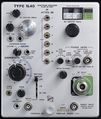
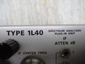
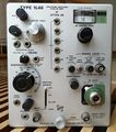
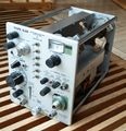
The '''Tektronix 1L40''' is a spectrum analyzer plug-in for [[500-series scopes]]. | The '''Tektronix 1L40''' is a spectrum analyzer plug-in for [[500-series scopes]]. | ||
It covers the frequency range from 1.5 GHz to 40 GHz. | It covers the frequency range from 1.5 GHz to 40 GHz using four different removable front-end mixer modules. | ||
By default the 1L40 comes with a coaxial mixer, Tek part number [[119-0096-00]], which works up to 12.4 GHz using a [[1N415D]] detector diode. | |||
By default the 1L40 comes with a coaxial mixer, | |||
Tek part number 119-0096-00, which works up to 12.4 GHz | |||
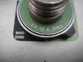
Higher frequencies are covered by three waveguide mixers: | |||
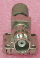
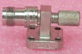
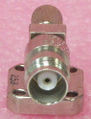
* [[119-0097-00]]: 12.4 GHz to 18 GHz | |||
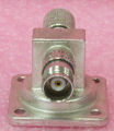
* [[119-0098-00]]: 18 GHz to 26.5 GHz | |||
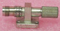
* [[119-0099-00]]: 26.5 GHz to 40 GHz | |||
Note that the 1L40's display of RF signals is actually back-to-front — lower frequencies are displayed to the right, higher frequencies to the left. | |||
This is because the 1<sup>st</sup> LO is above the input signal frequency, yet the display shows the IF sweep from low to high left-to-right, so the displayed spectrum is inverted. | |||
The 1L40 is also capable of displaying signals in its IF range of 150-250 MHz, because its input is unfiltered so everything passes straight through to the second mixer. | |||
In this case, however, the display is left-to-right. | |||
Type 1L40 was produced for only 3 years, making it the shortest-lived letter-series plug-in. | |||
{{MissingSpecs}} | |||
==Pictures== | ==Pictures== | ||
<gallery> | <gallery> | ||
Tek 1l40 front.jpg|1L40 Front | Tek 1l40 bottom2.jpeg | ||
Tek 1l40 cat.jpg|Front | Tek 1l40 front2.jpeg | ||
Bent tooth gear and screw.jpg|Bent tooth on 1L40 tuning gear provides limit stop in both directions. | Tek 1l40 left2.jpeg | ||
Tek 1l40 rear2.jpeg | |||
Tek 1l40 right2.jpeg | |||
Tek 1l40 top2.jpeg | |||
Tek 1l40 front.jpg | 1L40 Front | |||
Tek 1l40 cat.jpg | Front view from catalog | |||
Bent tooth gear and screw.jpg | Bent tooth on 1L40 tuning gear provides limit stop in both directions. | |||
Tek 1L40 1.jpg | Tek 1L40 1.jpg | ||
Tek 1L40 2.jpg | Tek 1L40 2.jpg | ||
| Line 54: | Line 53: | ||
Tek 1L40 8.jpg | Tek 1L40 8.jpg | ||
Tek 1L40 9.jpg | Tek 1L40 9.jpg | ||
Tek 1l40 mixers.png|External Mixers and Adaptor | Tek 1l40 mixers.png |External Mixers and Adaptor | ||
Tek 119-0097-00 1.jpg|119-0097-00 | Tek 119-0097-00 1.jpg | 119-0097-00 | ||
Tek 119-0097-00 2.jpg|119-0097-00 | Tek 119-0097-00 2.jpg | 119-0097-00 | ||
Tek 119-0098-00 1.jpg|119-0098-00 | Tek 119-0098-00 1.jpg | 119-0098-00 | ||
Tek 119-0098-00 2.jpg|119-0098-00 | Tek 119-0098-00 2.jpg | 119-0098-00 | ||
Tek 119-0099-00 1.jpg|119-0099-00 | Tek 119-0099-00 1.jpg | 119-0099-00 | ||
Tek 119-0099-00 2.jpg|119-0099-00 | Tek 119-0099-00 2.jpg | 119-0099-00 | ||
1L40_front.jpg|Front view | 1L40_front.jpg | Front view | ||
1L40_threequarter.jpg|Threequarter view | 1L40_threequarter.jpg | Threequarter view | ||
1L40_right.jpg|Right side view. Note the housing for the removable input mixer at bottom left, and the tuned cavity for the 1st local oscillator at the top. | 1L40_right.jpg | Right side view. Note the housing for the removable input mixer at bottom left, and the tuned cavity for the 1st local oscillator at the top. | ||
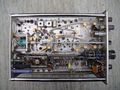
1L40_left.jpg|Left side view | 1L40_left.jpg | Left side view | ||
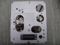
1L40_rear.jpg|Rear view. Note the selector switch to adapt the sweep input voltage to different models in the 500 series range. | 1L40_rear.jpg | Rear view. Note the selector switch to adapt the sweep input voltage to different models in the 500 series range. | ||
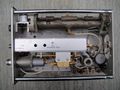
1L40_bottom.jpg|Bottom view | 1L40_bottom.jpg | Bottom view | ||
1L40_top.jpg|Top view. Cavity for the 1st local oscillator is on the right, and the tuning mechanism is visible. IF filters and attenuators are in the can in the middle. | 1L40_top.jpg | Top view. Cavity for the 1st local oscillator is on the right, and the tuning mechanism is visible. IF filters and attenuators are in the can in the middle. | ||
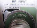
1L40_input_closeup.jpg|Input connector. This is the basic 1.5-12. | 1L40_input_closeup.jpg | Input connector. This is the basic 1.5-12.4 GHz input, which can be removed and replaced with an extension cable to waveguide mixers for higher frequencies. | ||
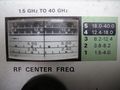
1L40_dial_closeup.jpg|Closeup of RF centre frequency dial. Fundamental range is at the bottom with harmonics above. | 1L40_dial_closeup.jpg | Closeup of RF centre frequency dial. Fundamental range is at the bottom with harmonics above. | ||
1L40_dispersion_switch_closeup.jpg|Closeup of part of the dispersion range switch assembly. Note the two little fingers attached to the shaft which operate the toggle switch. | 1L40_dispersion_switch_closeup.jpg | Closeup of part of the dispersion range switch assembly. Note the two little fingers attached to the shaft which operate the toggle switch. | ||
1L40_in_535A_2100MHz.jpg|1L40 in 535A mainframe tuned to | 1L40_in_535A_2100MHz.jpg | 1L40 in 535A mainframe tuned to 2100 MHz cellular band showing signals. 5 MHz/div dispersion. | ||
1L40_2100MHz_closeup.jpg|Tuned to | 1L40_2100MHz_closeup.jpg | Tuned to 2100 MHz cellular band (5 MHz/div dispersion) showing 3 G data downlinks from various operators. From the right: Orange, T-Mobile, Plus and Play. Photo taken in Warsaw, Poland, January 2018. | ||
1L40_IF.jpg|Signals displayed straight through the plugin's 150- | 1L40_IF.jpg | Signals displayed straight through the plugin's 150-250 MHz IF. Dispersion 5 MHz/div, centre frequency 200 MHz. The peak on the left is the local DAB radio multiplex on channel 6B, 183.648 MHz. The hump to the right of that is the local DVB-T multiplex 'Mux 8' on channel 7. Photo taken in Warsaw, Poland, January 2018. | ||
</gallery> | </gallery> | ||
| Line 79: | Line 78: | ||
[https://drive.google.com/open?id=0B-Q3jyZPb-C1VUx2TUlObmpJdHc&authuser=0 Video of Tuning Limit Stop Mechanism] | [https://drive.google.com/open?id=0B-Q3jyZPb-C1VUx2TUlObmpJdHc&authuser=0 Video of Tuning Limit Stop Mechanism] | ||
==Components== | |||
[[Category:500 series plugins]] | {{Parts|1L40}} | ||
[[Category:500 series spectrum analyzer plugins]] | |||
Latest revision as of 01:50, 22 September 2023

The Tektronix 1L40 is a spectrum analyzer plug-in for 500-series scopes. It covers the frequency range from 1.5 GHz to 40 GHz using four different removable front-end mixer modules.
By default the 1L40 comes with a coaxial mixer, Tek part number 119-0096-00, which works up to 12.4 GHz using a 1N415D detector diode.
Higher frequencies are covered by three waveguide mixers:
- 119-0097-00: 12.4 GHz to 18 GHz
- 119-0098-00: 18 GHz to 26.5 GHz
- 119-0099-00: 26.5 GHz to 40 GHz
Note that the 1L40's display of RF signals is actually back-to-front — lower frequencies are displayed to the right, higher frequencies to the left. This is because the 1st LO is above the input signal frequency, yet the display shows the IF sweep from low to high left-to-right, so the displayed spectrum is inverted.
The 1L40 is also capable of displaying signals in its IF range of 150-250 MHz, because its input is unfiltered so everything passes straight through to the second mixer. In this case, however, the display is left-to-right.
Type 1L40 was produced for only 3 years, making it the shortest-lived letter-series plug-in.
Key Specifications
- please add
Pictures
-

-
-
-
-
-

-
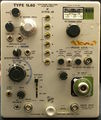
1L40 Front
-
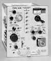
Front view from catalog
-
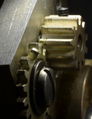
Bent tooth on 1L40 tuning gear provides limit stop in both directions.
-
-
-
-
-
-
-
-
-
-
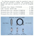
External Mixers and Adaptor
-
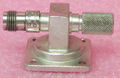
119-0097-00
-
119-0097-00
-
119-0098-00
-
119-0098-00
-
119-0099-00
-
119-0099-00
-
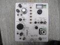
Front view
-
Threequarter view
-
Right side view. Note the housing for the removable input mixer at bottom left, and the tuned cavity for the 1st local oscillator at the top.
-
Left side view
-
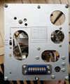
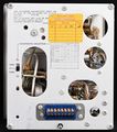
Rear view. Note the selector switch to adapt the sweep input voltage to different models in the 500 series range.
-
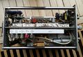
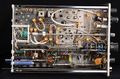
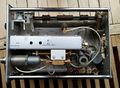
Bottom view
-
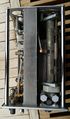
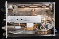
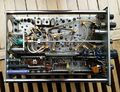
Top view. Cavity for the 1st local oscillator is on the right, and the tuning mechanism is visible. IF filters and attenuators are in the can in the middle.
-
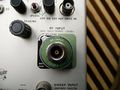
Input connector. This is the basic 1.5-12.4 GHz input, which can be removed and replaced with an extension cable to waveguide mixers for higher frequencies.
-
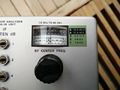
Closeup of RF centre frequency dial. Fundamental range is at the bottom with harmonics above.
-
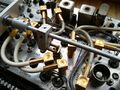
Closeup of part of the dispersion range switch assembly. Note the two little fingers attached to the shaft which operate the toggle switch.
-
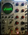
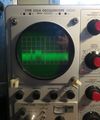
1L40 in 535A mainframe tuned to 2100 MHz cellular band showing signals. 5 MHz/div dispersion.
-
Tuned to 2100 MHz cellular band (5 MHz/div dispersion) showing 3 G data downlinks from various operators. From the right: Orange, T-Mobile, Plus and Play. Photo taken in Warsaw, Poland, January 2018.
-
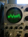
Signals displayed straight through the plugin's 150-250 MHz IF. Dispersion 5 MHz/div, centre frequency 200 MHz. The peak on the left is the local DAB radio multiplex on channel 6B, 183.648 MHz. The hump to the right of that is the local DVB-T multiplex 'Mux 8' on channel 7. Photo taken in Warsaw, Poland, January 2018.


Video
Video of Tuning Limit Stop Mechanism
Components
Some Parts Used in the 1L40
| Part | Part Number(s) | Class | Description | Used in |
|---|---|---|---|---|
| 1N3717 | 152-0381-00 • 152-0125-00 | Discrete component | 4.7 mA, 25 pF tunnel diode | 1L40 • 1S1 • 1S2 • 11B1 • 11B2 • 11B2A • 147A • 1470 • 148 • 21A • 22A • 3B4 • 3B5 • 408 • 432 • 434 • 453 • 453A • 454 • 466 • 491 • 5T3 • 544 • RM544 • 546 • RM546 • 547 • RM547 • 556 • RM556 • 7B70 • 7B71 • 7D11 |
| STD704 | 152-0125-00 | Discrete component | 4.7 mA tunnel diode | 1L40 • 1S1 • 11B1 • 11B2 • 11B2A • 147 • R147 • 147A • R147A • 1470 • 148 • R148 • 148-M • 149 • R149 • 149A • R149A • 21A • 22A • 3B4 • 3B5 • 408 • 432 • 434 • 453 • 453A • 454 • 464 • 465 • 466 • 491 • 5T3 • 544 • RM544 • 546 • RM546 • 547 • RM547 • 556 • RM556 • 7B70 • 7B71 • 7D11 |