L: Difference between revisions
m (→top: clean up, replaced: {{Plugin Sidebar 2 → {{Plugin Sidebar | designers=, title=Tektronix → manufacturer=Tektronix | model=) |
No edit summary |
||
| Line 6: | Line 6: | ||
introduced=1957 | | introduced=1957 | | ||
discontinued=1973 | | discontinued=1973 | | ||
series= | series=500-series scopes | | ||
manuals= | manuals= | ||
* [http://w140.com/mmm/tek-l.pdf Tektronix Type L Manual (PDF)] | * [http://w140.com/mmm/tek-l.pdf Tektronix Type L Manual (PDF)] | ||
| Line 25: | Line 25: | ||
It was dropped after 1972. | It was dropped after 1972. | ||
[[K]], | [[K]], L, and [[T]] are tied for longest production life, at 16 years. | ||
[[B]], [[D]], and [[G]] are next at 15 years. | [[B]], [[D]], and [[G]] are next at 15 years. | ||
Revision as of 09:04, 9 August 2021

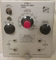
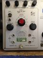
The Tektronix Type L is an amplifier plug-in for 500-series scopes.
The Type L is a Type K plus a 10x-gain AC-coupled preamp that extends the maximum sensitivity to 5 mV/div. Bandwidth in a 545 is 30 MHz at 50 mV/div and above, 3 Hz-24 MHz at 20 mV/div and below.
Type 53/54L was introduced in 1957 along with the 536 and its companion 53/54T sweep plug-in. It was renamed the Type L in 1959. It was the fastest 5 mV plug-in until the 1A1 in 1964. It was dropped after 1972.
K, L, and T are tied for longest production life, at 16 years. B, D, and G are next at 15 years.
Late versions have a BNC connector instead of a UHF connector.
Lavoie Laboratories produced an unauthorized clone, the LA-265-L.
Key Specifications
- please add
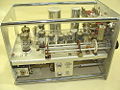
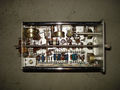
Internals
The input signal traverses a frequency-compensated attenuator network controlled by the Volts/cm switch, and is then coupled to the first cathode follower tube (V5832), a 5654/6AK5W RF pentode. The screen supply of this cathode follower is switched from +100 V to a decoupling network fed from the +225 V rail when the ×10 Mode is selected.
The output of input amplifier is then switched via a 10× amplifier (if ×10 mode is selected) or directly to the paraphase or phase inverter made up of two 12AU6 tubes. This stage converts the input signal to a differential push-pull output. This output is passed to the final output drivers, which are two cathode follower sections with a pair of 12AT7 tubes. The differential output is then passed to pin 1 and 3 of the connector to drive the vertical amplifier inside the chassis.
The ×10 amplifier stage is built with three 5654/6AK5W tubes, the first two of which are configured as amplifiers, and the last one as an output cathode follower.
The diode D5972 on the first 5654/6AK5W amplifier tube's cathode (V5942) is used to protect the cathode bypass capacitor C5972, a 500 μF/6 V electrolytic, in case someone would pull out V5942 with power applied, in which case the cathode bias of −150 V would come across C5972 and destroy it.
Heater supplies for the tubes are derived from the +75 VDC supply available at pin 15 of the mainframe interface, to avoid any mains interference/hum from the regular AC heater supply.
Pictures
-
-
-
-
-
-
Type L in 541A
-
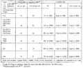
Performance in Different Scopes
-
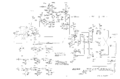
Schematic


