S-51: Difference between revisions
(template change) |
No edit summary |
||
| (15 intermediate revisions by 3 users not shown) | |||
| Line 1: | Line 1: | ||
{{Plugin Sidebar | {{Plugin Sidebar | ||
|manufacturer=Tektronix | |||
summary=Synchronizing Head | | |series=7000 and 3S series sampling heads | ||
image= | |type=S-51 | ||
caption=S-51 head | |summary=Synchronizing Head | ||
|image=Tek s-51 1.jpg | |||
introduced=1969 | | |caption=S-51 head | ||
discontinued= | |introduced=1969 | ||
manuals= | |discontinued=1989 | ||
* [ | |designers=Murlan Kaufman | ||
|manuals= | |||
* [[Media:070-0898-00.pdf|Tektronix S-51 Manual]] | |||
* [[Media:Tek s-51 fcp march 1969.pdf|Tektronix S-51 Factory Calibration Procedure, March 1969]] (OCR) | |||
}} | }} | ||
The '''Tektronix S-51''' is a synchronizing head for [[sampling oscilloscope]] systems such as the [[3S2]] or [[7S12]] which use S-series sampling heads. | |||
It was designed by [[Murlan Kaufman]]. | |||
From a periodic input signal in the 1 GHz to 18 GHz range, the S-51 generates trigger pulses which have a fixed time relationship with the input signal. | |||
The input is a 50 Ω [[SMA connector]]. The trigger output signal is available through a [[BSM connector]] on the front panel as well as through the internal interface. | |||
From a periodic input signal in the 1 GHz to 18 GHz range, the S-51 generates trigger | |||
pulses which have a fixed time relationship with the input signal. | |||
The input is a 50 Ω [[ | |||
through a [[ | |||
Equivalent-time sampling equipment generally requires the input signal to be repetitive. | Equivalent-time sampling equipment generally requires the input signal to be repetitive. | ||
| Line 23: | Line 24: | ||
This is true of all oscilloscopes that use synchronization instead of triggering. | This is true of all oscilloscopes that use synchronization instead of triggering. | ||
{{BeginSpecs}} | |||
{{Spec | Input impedance | 50 Ω real // 1 pF }} | |||
{{Spec | Input sensitivity | min. 100 mV<sub>p-p</sub>}} | |||
{{Spec | Kick-out | ma. 400 mV }} | |||
{{Spec | Jitter | max. 15 ps for input signals < 5 GHz, max. 10 ps above 5 GHz }} | |||
{{EndSpecs}} | |||
==Links== | |||
{{Documents|Link=S-51}} | |||
{{PatentLinks|S-51}} | |||
==Internals== | |||
The S-51 contains a [[tunnel diodes|tunnel diode]] sync oscillator that oscillates at about 200 MHz (165 MHz to 285 MHz). | The S-51 contains a [[tunnel diodes|tunnel diode]] sync oscillator that oscillates at about 200 MHz (165 MHz to 285 MHz). | ||
The input signal is coupled with this oscillator, resulting in injection locking. | The input signal is coupled with this oscillator, resulting in injection locking. | ||
| Line 30: | Line 43: | ||
The approximate range of f<sub>osc</sub> is adjustable. | The approximate range of f<sub>osc</sub> is adjustable. | ||
Trigger pulses are produced at | Trigger pulses are produced at the beginning of a cycle of the sync oscillator. | ||
After each trigger pulse is produced, the sync oscillator is turned off for about 15 microseconds. | After each trigger pulse is produced, the sync oscillator is turned off for about 15 microseconds. | ||
As a result, the S-51 produces trigger pulses at a repetition rate of approximately 67 kHz. | As a result, the S-51 produces trigger pulses at a repetition rate of approximately 67 kHz. | ||
Even without any input, the S-51 will produce trigger pulses at approximately 67 kHz. | Even without any input, the S-51 will produce trigger pulses at approximately 67 kHz. | ||
The tunnel diode, D2 in the schematic, that forms the sync oscillator is Tek part number [[153-0041-00]]. | |||
==Pictures== | ==Pictures== | ||
<gallery> | <gallery> | ||
Tek s-51 1.jpg | |||
Tek s-51 2.jpg | |||
S-51.jpg | |||
Tek s-51 internal1.jpg | |||
Tek s-51 internal2.jpg | |||
Tek s-51 internal3.jpg | |||
S-51 schem2.png | |||
Tek s51 on cart.jpg | |||
Tek s51 front2.jpg | |||
</gallery> | </gallery> | ||
[[Category:7000 and 3S series sampling heads]] | [[Category:7000 and 3S series sampling heads]] | ||
Latest revision as of 10:52, 19 June 2024
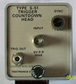
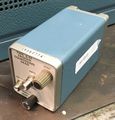
The Tektronix S-51 is a synchronizing head for sampling oscilloscope systems such as the 3S2 or 7S12 which use S-series sampling heads. It was designed by Murlan Kaufman.
From a periodic input signal in the 1 GHz to 18 GHz range, the S-51 generates trigger pulses which have a fixed time relationship with the input signal. The input is a 50 Ω SMA connector. The trigger output signal is available through a BSM connector on the front panel as well as through the internal interface.
Equivalent-time sampling equipment generally requires the input signal to be repetitive. The S-51 is more restrictive; it is specifically designed for periodic signals. This is true of all oscilloscopes that use synchronization instead of triggering.
Key Specifications
| Input impedance | 50 Ω real // 1 pF |
|---|---|
| Input sensitivity | min. 100 mVp-p |
| Kick-out | ma. 400 mV |
| Jitter | max. 15 ps for input signals < 5 GHz, max. 10 ps above 5 GHz |
Links
Documents Referencing S-51
| Document | Class | Title | Authors | Year | Links |
|---|---|---|---|---|---|
| Service Scope 52 Oct 1968.pdf | Article | The State of the Art in Sampling | Al Zimmerman | 1968 | S-1 • S-2 • S-3 • S-4 • S-50 • S-51 • 285 • 3S1 • 3S2 • 3S5 • 3S6 • 3T2 • 3T5 • 3T6 • 3T77A • 568 • 230 |
Internals
The S-51 contains a tunnel diode sync oscillator that oscillates at about 200 MHz (165 MHz to 285 MHz). The input signal is coupled with this oscillator, resulting in injection locking. When locked, fosc is a subharmonic of fin:
- fosc = fin / n, where n is an integer between 5 and 90, inclusive
- fosc is between 165 MHz and 285 MHz.
The approximate range of fosc is adjustable.
Trigger pulses are produced at the beginning of a cycle of the sync oscillator. After each trigger pulse is produced, the sync oscillator is turned off for about 15 microseconds. As a result, the S-51 produces trigger pulses at a repetition rate of approximately 67 kHz. Even without any input, the S-51 will produce trigger pulses at approximately 67 kHz.
The tunnel diode, D2 in the schematic, that forms the sync oscillator is Tek part number 153-0041-00.


