308: Difference between revisions
No edit summary |
No edit summary |
||
| (35 intermediate revisions by 4 users not shown) | |||
| Line 1: | Line 1: | ||
[[ | {{Instrument Sidebar | ||
|class=Logic Analyzer | |||
The '''Tektronix 308''' is a portable 8-channel, 20 MHz "data analyzer" (logic analyzer) with parallel timing, parallel state, serial (up to 9600 bps) and signature analysis modes. | |manufacturer=Sony/Tektronix | ||
|series= | |||
|model=308 | |||
|summary=20 MHz 8-ch Logic Analyzer | |||
|image=308-timing.jpg | |||
|caption=Sony/Tektronix 308 | |||
|introduced=1980 | |||
|discontinued=1986 | |||
|designers= | |||
|manuals= | |||
* [[Media:070-2663-00.pdf | Tek 308 Operator's Manual]] | |||
* [[Media:070-2662-00.pdf | Tek 308 Service manual, Oct 1979]] (OCR) | |||
* [[Media:070-2662-00 revised september 1986.pdf|Tek 308 Service manual, Sept 1986]] | |||
* [[Media:Tek_308_logic_analyzer_+_probes_(1979)_SM.pdf | Tek 308 Service manual + probes]] (OCR) | |||
====ROM images==== | |||
* [[Media:160-0768-00.bin|160-0768-00.bin]] U430 - 0x0000 | |||
* [[Media:160-0769-00.bin|160-0769-00.bin]] U432 - 0x2000 | |||
* [[Media:160-0770-00.bin|160-0770-00.bin]] U434 - 0x4000 | |||
* [[Media:160-0797-00.bin|160-0797-00.bin]] U486 - CharGen | |||
}} | |||
The '''Sony/Tektronix 308''' is a portable 8-channel, 20 MHz "data analyzer" (logic analyzer) with parallel timing, parallel state, serial (up to 9600 bps) and [[signature analysis]] modes. | |||
The 308 uses two probes, the standard [[P6451]] 8-channel + clock data acquisition probe, and the optional 16-channel [[P6406]] word recognizer probe. Both use [[012-0747-00]] cable harnesses to attach to the data source. | The 308 uses two probes, the standard [[P6451]] 8-channel + clock data acquisition probe, and the optional 16-channel [[P6406]] word recognizer probe. Both use [[012-0747-00]] cable harnesses to attach to the data source. | ||
{{BeginSpecs}} | {{BeginSpecs}} | ||
{{Spec | | {{SpecGroup | Inputs}} | ||
{{Spec | Serial | {{Spec | Data | Eight data channels + 1 clock channel ([[P6451]] probe), impedance 1 MΩ // 5 pF, max. ±40 V nondestructive, logic threshold fixed 1.4 V (TTL) or variable from −12 V to +12 V }} | ||
{{Spec | Qualifier | {{Spec | Word recognizer | Sixteen TTL inputs (+40/−400 μA max.), max. +15/−1 V }} | ||
{{Spec | Serial | [[BNC connector]], 1 MΩ // 40 pF, max. ±250 V on BNC; used with [[P6107]] probe, 10 MΩ // 13 pF, max. ±500 V}} | |||
{{Spec | Qualifier | [[BNC connector]], 10 kΩ, max. +10/−5 V }} | |||
{{SpecGroup | Acquisition}} | |||
{{Spec | Clock | 50 ns to 200 ms per sample (1-2-5 sequence) or external down to 50 ns }} | |||
{{Spec | Timing | Data setup time min. 25 ns, hold time min. 0 ns }} | |||
{{Spec | Memory | 2 × 252 eight-bit words (acquisition + reference) }} | |||
{{Spec | Trigger mode | PRE (trigger at memory location 240) or POST (location 13) }} | |||
{{Spec | Trigger delay | 0-65535 clock periods }} | |||
{{Spec | Serial data | 5, 6, 7 or 8 bits per character, asynchronous (50, 75, 110, 134.5, 150, 200, 300, 600, 1200, 1900, 2400, 4800 or 9600 bits/s or external up to 9600 bits/s) or synchronous up to 9600 bits/s }} | |||
{{Spec | Signature analysis | 20 MHz via serial probe input (data) and P6451 (0 start, 1 stop, C clock); up to 8 recent signatures displayed }} | |||
{{SpecGroup | Display }} | |||
{{Spec | CRT | [[154-0814-00]], 6.8 cm × 5.4 cm, P4 phosphor (white) }} | |||
{{SpecGroup | General }} | |||
{{Spec | Power | 90-132 V or 180-250 V, 48-440 Hz }} | |||
{{Spec | Weight | 3.7 kg (8.16 lb) }} | |||
{{EndSpecs}} | {{EndSpecs}} | ||
==Links== | |||
* [https://www.radiomuseum.org/r/sonytek_data_analyzer_308.html Tek 308 @ radiomuseum.org] | |||
{{Documents|Link=308}} | |||
{{PatentLinks|308}} | |||
==Internals== | |||
The 308 is built around an [[Intel 8085]]A microprocessor. The display is a magnetically deflected raster-scan CRT. | |||
The only Tek-specific IC in the 308 is a [[155-0067-02]] SMPS controller. | |||
==Pictures== | ==Pictures== | ||
<gallery> | <gallery> | ||
308-timing.jpg | 308 display, timing mode (binary counter example) | |||
308-state.jpg | 308 display, state mode (binary counter example) | |||
Tek 308 3.jpg | Tek 308 3.jpg | ||
Tek 308 4.jpg | Tek 308 4.jpg | ||
| Line 23: | Line 64: | ||
Tek 308 6.jpg | Tek 308 6.jpg | ||
Tek 308 7.jpg | Tek 308 7.jpg | ||
Tek 308 11.jpg | Tek 308 11.jpg | ||
Tek 308 101.jpg | |||
Tek 308 102.jpg | |||
Tek 308 103.jpg | |||
Tek 308 104.jpg | |||
Tek 308 105.jpg | |||
Tek 308 106.jpg | |||
Tek 308 1.jpg | |||
Tek 308 2.jpg | |||
Tek 308 10.jpg | |||
</gallery> | |||
'''Internals''' | |||
<gallery> | |||
Tek308 top l.jpg | Top left | |||
Tek308 top r1.jpg | Top right | |||
Tek308 top r2.jpg | Top right (2) | |||
Tek308_unfolding.jpg | Boards unfolding | |||
Tek308_unfolding_2.jpg | Boards unfolding (2) | |||
Tek308 input.jpg | Input board | |||
Tek308_trigger.jpg | Trigger board | |||
Tek308 boards back.jpg | back side of input and trigger boards | |||
Tek308 sig.jpg | Signature/Serial board | |||
Tek308 cpu.jpg | CPU board | |||
Tek308 crt.jpg | CRT module | |||
Tek308 psu top.jpg | Power supply, top | |||
Tek308 psu bot.jpg | Power supply, bottom | |||
308_PSU_Internals1.jpg | Internal side of the power supply | |||
308_mains_input_PCB.jpg | Internal side of the power supply | |||
Tek308 bot.jpg | Bottom (CRT board and card cage) | |||
Tek_308_under_SN303537-UP.jpg | Bottom CRT board SN303537-UP | |||
</gallery> | |||
'''Probes''' | |||
<gallery> | |||
Tek 308 8.jpg | [[P6451]] probe | |||
Tek 308 9.jpg | P6451 probe | |||
P6451-int-1.jpg | P6451 probe internal, PCB front | |||
P6451-int-2.jpg | P6451 probe internal, PCB back | |||
p6406-1.jpg | [[P6406]] word recognizer probe | |||
p6406-2.jpg | P6406 case close-up | |||
p6406-3.jpg | P6406 PCB front | |||
p6406-4.jpg | P6406 PCB back | |||
P64xx-jumper.jpg | Using P64xx probes with jumper wires | |||
</gallery> | </gallery> | ||
==Components== | |||
{{Parts|308}} | |||
{{PatentLinks|308}} | |||
[[Category:Logic | [[Category:Logic analyzers]] | ||
Latest revision as of 05:13, 14 October 2024
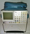
The Sony/Tektronix 308 is a portable 8-channel, 20 MHz "data analyzer" (logic analyzer) with parallel timing, parallel state, serial (up to 9600 bps) and signature analysis modes.
The 308 uses two probes, the standard P6451 8-channel + clock data acquisition probe, and the optional 16-channel P6406 word recognizer probe. Both use 012-0747-00 cable harnesses to attach to the data source.
Key Specifications
| — Inputs — | |
| Data | Eight data channels + 1 clock channel (P6451 probe), impedance 1 MΩ // 5 pF, max. ±40 V nondestructive, logic threshold fixed 1.4 V (TTL) or variable from −12 V to +12 V |
| Word recognizer | Sixteen TTL inputs (+40/−400 μA max.), max. +15/−1 V |
| Serial | BNC connector, 1 MΩ // 40 pF, max. ±250 V on BNC; used with P6107 probe, 10 MΩ // 13 pF, max. ±500 V |
| Qualifier | BNC connector, 10 kΩ, max. +10/−5 V |
| — Acquisition — | |
| Clock | 50 ns to 200 ms per sample (1-2-5 sequence) or external down to 50 ns |
| Timing | Data setup time min. 25 ns, hold time min. 0 ns |
| Memory | 2 × 252 eight-bit words (acquisition + reference) |
| Trigger mode | PRE (trigger at memory location 240) or POST (location 13) |
| Trigger delay | 0-65535 clock periods |
| Serial data | 5, 6, 7 or 8 bits per character, asynchronous (50, 75, 110, 134.5, 150, 200, 300, 600, 1200, 1900, 2400, 4800 or 9600 bits/s or external up to 9600 bits/s) or synchronous up to 9600 bits/s |
| Signature analysis | 20 MHz via serial probe input (data) and P6451 (0 start, 1 stop, C clock); up to 8 recent signatures displayed |
| — Display — | |
| CRT | 154-0814-00, 6.8 cm × 5.4 cm, P4 phosphor (white) |
| — General — | |
| Power | 90-132 V or 180-250 V, 48-440 Hz |
| Weight | 3.7 kg (8.16 lb) |
Links
Documents Referencing 308
| Document | Class | Title | Authors | Year | Links |
|---|---|---|---|---|---|
| Tekscope 1980 V12 N1.pdf | Article | New Products | 1980 | 308 • SG505 • 8002A | |
| Tekscope 1980 V12 N2.pdf | Article | Portable Analyzer Speeds Test and Service of Microprocessor-Based System | Ed Averill • John Huber | 1980 | 308 |
Patents that may apply to 308
| Page | Title | Inventors | Filing date | Grant date | Links |
|---|---|---|---|---|---|
| Patent US 3976864A | Apparatus and method for testing digital circuits | Gary B. Gordon • George A. Haag • Jan R. Hofland • Daniel I. Kolody | 1974-09-03 | 1976-08-24 | Signature analysis • 308 • SA501 |
Internals
The 308 is built around an Intel 8085A microprocessor. The display is a magnetically deflected raster-scan CRT. The only Tek-specific IC in the 308 is a 155-0067-02 SMPS controller.
Pictures
-
308 display, timing mode (binary counter example)
-
308 display, state mode (binary counter example)
-
-
-
-
-
-
-
-
-
-
-
-
-
-
-
Internals
-
Top left
-
Top right
-
Top right (2)
-
Boards unfolding
-
Boards unfolding (2)
-
Input board
-
Trigger board
-
back side of input and trigger boards
-
Signature/Serial board
-
CPU board
-
CRT module
-
Power supply, top
-
Power supply, bottom
-
Internal side of the power supply
-
Internal side of the power supply
-
Bottom (CRT board and card cage)
-
Bottom CRT board SN303537-UP
Probes
-
P6451 probe
-
P6451 probe
-
P6451 probe internal, PCB front
-
P6451 probe internal, PCB back
-
P6406 word recognizer probe
-
P6406 case close-up
-
P6406 PCB front
-
P6406 PCB back
-
Using P64xx probes with jumper wires
Components
Some Parts Used in the 308
| Part | Part Number(s) | Class | Description | Used in |
|---|---|---|---|---|
| 154-0814-00 | 154-0814-00 | CRT | CRT | 308 |
| 155-0067-02 | 155-0067-00 • 155-0067-02 • 155-0067-03 | Monolithic integrated circuit | SMPS controller | 7704A • 7834 • 7844 • 7854 • 7904 • R7903 • 7904 • 7904A • 7934 • R7912 • 7912AD • 7912HB • 7934 • 7104 • R7103 • 308 • 434 • 485 • 690 • P7001 |
| 2316E | Monolithic integrated circuit | 2K×8 ROM | 308 | |
| 2364 | Monolithic integrated circuit | 8K×8 ROM | 308 | |
| Intel 8085A | 156-1088-00 | Monolithic integrated circuit | 8-bit microprocessor | 308 • 468 • 4025 • 7A42 • 7D02 • AFG5101 • AFG5102 • PFG5105 |
Patents that may apply to 308
| Page | Title | Inventors | Filing date | Grant date | Links |
|---|---|---|---|---|---|
| Patent US 3976864A | Apparatus and method for testing digital circuits | Gary B. Gordon • George A. Haag • Jan R. Hofland • Daniel I. Kolody | 1974-09-03 | 1976-08-24 | Signature analysis • 308 • SA501 |


