491: Difference between revisions
Jump to navigation
Jump to search
(New page: The Tektronix 491 is a spectrum analyzer introduced in August 1966.) |
No edit summary |
||
| (52 intermediate revisions by 3 users not shown) | |||
| Line 1: | Line 1: | ||
The Tektronix 491 is a spectrum analyzer [[introduced in 1966|introduced in August 1966]]. | {{Instrument Sidebar | ||
|manufacturer=Tektronix | |||
|class=Spectrum Analyzer | |||
|model=491 | |||
|summary=40 GHz Spectrum Analyzer | |||
|image=Tek 491.jpg | |||
|caption=Tektronix 491 | |||
|introduced=1966 | |||
|discontinued=1980 | |||
|designers=Gene Kauffman; | |||
|manuals= | |||
* [[Media:070-0598-01.pdf|Tektronix 491 Instruction Manual 070-0598-01]]'' | |||
* [[Media:Tektronix_491_Maintenance_Manual_ARMY.pdf | Tektronix 491 Instruction Manual (US Army TM 9-6625-2467-15)]] | |||
* [[Media:Tek_491_Catalog_Spec_1967.pdf | Tektronix 491 Introduction Spec]] (OCR) | |||
* [[Media:Tek_491_Catalog_Spec_1979.pdf | Tektronix 491 Final Spec]] (OCR) | |||
<small> | |||
'''Modifications and Calibration''' | |||
* [[Media:050-0692-03.pdf | Tektronix 491 Band C Oscillator Replacement Modification]] (OCR) | |||
* [[Media:Tek 491 mod wa.pdf | Tektronix 491 Mod WA]] | |||
* [[Media:Tek 491 fcp nov 1966.pdf | Tektronix 491 Factory Calibration Procedure, November 1966]] | |||
</small> | |||
}} | |||
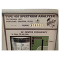
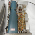
The '''Tektronix 491''' is a spectrum analyzer with a frequency range of 10 MHz to 12.4 GHz (up to 40 GHz with external waveguide mixers). | |||
The 491 was [[introduced in 1966|introduced in August 1966]]. Due to severe performance limitations, the 491 was replaced by the completely redesigned [[492]] in 1980. | |||
{{BeginSpecs}} | |||
{{Spec | Frequency | | |||
* Coaxial Input Bands 10 MHz to 12.4 GHz (Band A-1 10 MHz to 275 MHz; Bands B-2 & 3: 275 MHz to 2 GHz; Bands C-4, 5, & 6: 1.5 GHz to 12.4 GHz) | |||
* External Waveguide mixers: 12.4 MHz to 40 GHz (Band 7 (Ku) 12.4 GHz to 18 GHz; Band 8 (K) 18 GHz to 26.5 GHz, (Ka) 18 GHz to 40 GHz)}} | |||
{{Spec | Dispersion | (plus 0 Hz) 200 kHz/div to 10 MHz/div in 1−2−5 sequence }} | |||
{{Spec | Resolution Bandwidth | 1 kHz to 100 kHz (6 dB) }} | |||
{{Spec | Input | 50 Ω, max. −30 dBm for linear operation, +15 dBm (25 mW) diode mixer power limit }} | |||
{{Spec | IF Attenuator | 0 dB to 51 dB, in combinations of 1, 2, 4, 8, 16, and 20 dB }} | |||
{{Spec | Sweep Speed | 0.5 s/div to 10 µs/div in 1, 2, 5 sequence; Uncalibrated to approx 1.25 s/div }} | |||
{{Spec | Triggering Modes | Internals, External, and Line; 100 V maximum input (DC + peak AC) }} | |||
{{Spec | Dynamic Range | 80 dB (Max sensitivity of −110 dBm minus Max input power of −30 dBm); display range ≥40 dB }} | |||
{{Spec | Calibrator | 200 MHz }} | |||
{{Spec | Weight | 13.6 kg / 30 lbs (Rackmount version 18 kg / 40 lbs) }} | |||
{{Spec | Power | 90−136 and 180−272 V<sub>AC</sub> in six ranges, 48−440 Hz. At 115 V<sub>AC</sub>, 60 Hz, 55 W }} | |||
{{Spec | Front panel | | |||
* RF INPUT (A) [[BNC connector]] (50 Ω, 10 MHz to 275 MHz) | |||
* RF INPUT (B) [[N connector]] (50 Ω, 275 MHz to 2 GHz) | |||
* WAVEGUIDE (C) − receptacle that accommodates either a coaxial mixer, 119-0096-00, with an N connector input for 1.5 to 12.4 GHz, or a [[119-0104-00]] waveguide mixer adapter connecting to external mixers for up to 40 GHz. | |||
* MARKERS OUT/EXT REF FREQ IN [[BNC connector]]: 1 MHz marker output when INT REF FREQ set to ON, otherwise PLL reference frequency input (1−5 MHz, 1−5 V<sub>p-p</sub>) }} | |||
{{Spec | Rear panel | | |||
* TRIG IN [[BNC connector]] (20 Hz to 100 kHz, ≥0.2 V) | |||
* SAW OUT [[BNC connector]] (75 mV/div) | |||
* RECORDER [[BNC connector]] (≥4 mV/div of displayed signal in LIN mode, DC-coupled, into 600 Ω) }} | |||
{{EndSpecs}} | |||
==Options== | |||
* Opt. 01: Limit Frequency Range to 10 MHz to 2 GHz | |||
* Opt. 02: Limit Frequency Range to 1.5 GHz to 40 GHz | |||
==Prices== | |||
1979: $10,700 ($41,800 in 2022 Dollars) | |||
According to an [[Media:Tek Schottky Diodes Memo rot.pdf|internal memo]], in 1979 annual sales were estimated at 172 units. | |||
==Pictures== | |||
<gallery> | |||
Tek 491 front trace.jpg | |||
Tek 491 rear.jpg | |||
Tek 491 1.jpg | |||
Tek 491 2.jpg | |||
Tek 491 3.jpg | |||
Tek 491 4.jpg | |||
Tek 491 5.jpg | |||
Tek 491 6.jpg | |||
Tek 491 7.jpg | |||
Tek 491 8.jpg | |||
Tek 491 trace.jpg | |||
Tek 491 center freq.jpg | |||
Tek 491 internal.jpg | |||
Tek 491 283022 0.jpg | |||
Tek 491 283022 1.jpg | |||
Tek 491 283022 2.jpg | |||
Tek 491 283022 3.jpg | |||
Tek 491 283022 4.jpg | |||
Tek 491 283022 5.jpg | |||
Tek 491 freq dial.jpg | |||
Tek 491 top int.jpg | |||
Tek 491 vertamp.jpg | |||
Tek 491 lo.jpg | |||
Tek 491 bot int.jpg | |||
</gallery> | |||
==Components== | |||
{{Parts|491}} | |||
[[Category:Spectrum analyzers]] | |||
Latest revision as of 06:10, 27 April 2024
The Tektronix 491 is a spectrum analyzer with a frequency range of 10 MHz to 12.4 GHz (up to 40 GHz with external waveguide mixers). The 491 was introduced in August 1966. Due to severe performance limitations, the 491 was replaced by the completely redesigned 492 in 1980.
Key Specifications
| Frequency |
|
|---|---|
| Dispersion | (plus 0 Hz) 200 kHz/div to 10 MHz/div in 1−2−5 sequence |
| Resolution Bandwidth | 1 kHz to 100 kHz (6 dB) |
| Input | 50 Ω, max. −30 dBm for linear operation, +15 dBm (25 mW) diode mixer power limit |
| IF Attenuator | 0 dB to 51 dB, in combinations of 1, 2, 4, 8, 16, and 20 dB |
| Sweep Speed | 0.5 s/div to 10 µs/div in 1, 2, 5 sequence; Uncalibrated to approx 1.25 s/div |
| Triggering Modes | Internals, External, and Line; 100 V maximum input (DC + peak AC) |
| Dynamic Range | 80 dB (Max sensitivity of −110 dBm minus Max input power of −30 dBm); display range ≥40 dB |
| Calibrator | 200 MHz |
| Weight | 13.6 kg / 30 lbs (Rackmount version 18 kg / 40 lbs) |
| Power | 90−136 and 180−272 VAC in six ranges, 48−440 Hz. At 115 VAC, 60 Hz, 55 W |
| Front panel |
|
| Rear panel |
|
Options
- Opt. 01: Limit Frequency Range to 10 MHz to 2 GHz
- Opt. 02: Limit Frequency Range to 1.5 GHz to 40 GHz
Prices
1979: $10,700 ($41,800 in 2022 Dollars)
According to an internal memo, in 1979 annual sales were estimated at 172 units.
Pictures
Components
Some Parts Used in the 491
| Part | Part Number(s) | Class | Description | Used in |
|---|---|---|---|---|
| 155-0157-00 | 155-0157-00 | Monolithic integrated circuit | digital storage vertical control | 7L5 • 7L14 • 7L18 • 491 • 492 • 492A • 492BP • 492PGM • 494 • 494A • 495 • 496 • 497P |
| 155-0158-00 | 155-0158-00 | Monolithic integrated circuit | digital storage horizontal control | 7L5 • 7L14 • 7L18 • 491 • 492 • 492A • 492BP • 492PGM • 494 • 494A • 495 • 496 • 497P |
| 1N3714 | 152-0081-00 | Discrete component | 2.2 mA, 25 pF germanium tunnel diode | 546 • 547 • 556 • 21A • 22A • 3B1 • 3B2 • 3B3 • 422 • 491 • 283 |
| 1N3717 | 152-0381-00 • 152-0125-00 | Discrete component | 4.7 mA, 25 pF tunnel diode | 1L40 • 1S1 • 1S2 • 11B1 • 11B2 • 11B2A • 147A • 1470 • 148 • 21A • 22A • 3B4 • 3B5 • 408 • 432 • 434 • 453 • 453A • 454 • 466 • 491 • 5T3 • 544 • RM544 • 546 • RM546 • 547 • RM547 • 556 • RM556 • 7B70 • 7B71 • 7D11 |
| STD704 | 152-0125-00 | Discrete component | 4.7 mA tunnel diode | 1L40 • 1S1 • 11B1 • 11B2 • 11B2A • 147 • R147 • 147A • R147A • 1470 • 148 • R148 • 148-M • 149 • R149 • 149A • R149A • 21A • 22A • 3B4 • 3B5 • 408 • 432 • 434 • 453 • 453A • 454 • 464 • 465 • 466 • 491 • 5T3 • 544 • RM544 • 546 • RM546 • 547 • RM547 • 556 • RM556 • 7B70 • 7B71 • 7D11 |
| T4910 | CRT | CRT | 491 | |
| TD714 | 152-0402-00 | Discrete component | 2.2 mA, 25 pF tunnel diode | 1401 • 1401A • 283 • R283 • 3B2 • 3B3 • 422 • 491 • 546 • RM546 • 547 • RM547 • 556 • RM556 • SPG11 • SPG12 |
| Y1641 | 154-0506-00 • 154-0510-00 | Vacuum Tube (Triode) | SHF cermet triode | 1L20 • 491 |


