Tekprobe BNC connector: Difference between revisions
No edit summary |
No edit summary |
||
| Line 7: | Line 7: | ||
simple resistive readout pins on probes from the [[7000 series scopes|7000 series scope generation]] (e.g. | simple resistive readout pins on probes from the [[7000 series scopes|7000 series scope generation]] (e.g. | ||
a ×10 probe will connect this pad to ground through 11 kΩ, or short it to ground when the Identify button | a ×10 probe will connect this pad to ground through 11 kΩ, or short it to ground when the Identify button | ||
is pressed — see [[7000 series readout system]] for details). The smaller pads carry +15 V, +5 V and | is pressed — see [[7000 series readout system]] for details). The smaller pads carry +15 V, +5 V, −5 V and −15 V | ||
power, an offset voltage supplied and controlled by the mainframe, and a clock/data signal pair for serial | power, an offset voltage supplied and controlled by the mainframe, and a clock/data signal pair for serial | ||
communication between the mainframe and "smart" probes. | communication between the mainframe and "smart" probes. Probes are allowed to draw max. 1.25 W, max. 75 mA from the ±5 V rails, and max. 25 mA from the ±15 V rails. | ||
A [[Tekprobe SMA connector|similar standard]] exists based on [[SMA connector]]s, suitable for higher frequencies. | A [[Tekprobe SMA connector|similar standard]] exists based on [[SMA connector]]s, suitable for higher frequencies. | ||
Revision as of 08:57, 29 August 2018

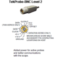
The Tekprobe BNC interface was introduced in 1986 and is widely used in 1990s Tektronix equipment to interface active probes (e.g. the P6243) to oscilloscopes.
It consists of a plain BNC connector that allows traditional BNC based connections such as from passive probes.
This connector is surrounded by contact pads carrying power and data. The two larger pad areas match the simple resistive readout pins on probes from the 7000 series scope generation (e.g. a ×10 probe will connect this pad to ground through 11 kΩ, or short it to ground when the Identify button is pressed — see 7000 series readout system for details). The smaller pads carry +15 V, +5 V, −5 V and −15 V power, an offset voltage supplied and controlled by the mainframe, and a clock/data signal pair for serial communication between the mainframe and "smart" probes. Probes are allowed to draw max. 1.25 W, max. 75 mA from the ±5 V rails, and max. 25 mA from the ±15 V rails.
A similar standard exists based on SMA connectors, suitable for higher frequencies.

Used in
| Scopes | Plug-ins | Probes |
|---|---|---|
Links
- What is the TekProbe interface? (Tektronix FAQ)
- What is the difference between the Tekprobe and TekConnect probe interfaces? (Tektronix FAQ)
Pictures
-
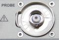
Tekprobe connector (socket)
-
Tekprobe-BNC interface
-
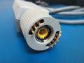
Tekprobe plug

