AM503A: Difference between revisions
No edit summary |
(split AM503 - AM503A/B) Tag: Removed redirect |
||
| Line 1: | Line 1: | ||
{{TM500 | |||
{{TM500 | type=AM503A | mfg=Tektronix | function=current probe amplifier | class=amplifier | |type=AM503A | ||
| image=Tek_am503a.jpg | introduced=1993 | discontinued=(?) | designers=Mike Mende |manuals= | |mfg=Tektronix | ||
|function=current probe amplifier | |||
|class=amplifier | |||
|image=Tek_am503a.jpg | |||
|introduced=1993 | |||
|discontinued=(?) | |||
|designers=Mike Mende | |||
|manuals= | |||
'''AM503A''' | |||
* [[Media:070-8174-01.pdf|AM503A Instruction Manual 070-8174-01]] | |||
* [[Media:AM503A_Schematics.pdf|AM503A Schematics]] | |||
'''AM503B/AM5030''' | |||
* [[Media:070-8766-05.pdf|AM503B/AM5030 Instruction Manual 070-8766-05]] | |||
* [[Media:070-8766-03.pdf|AM503B/AM5030 Instruction Manual 070-8766-03]] | |||
* [[Media:070-8770-01.pdf|AM503B/AM5030 Reference 070-8770-01]] | |||
* [[Media:070-9352-01.pdf|AM503B/5030, A6300 067-0271-00 Verification and Adjustment Kit Manual 070-9352-01]] | |||
* [[Media:AM503B_AM5030_Calibration_Adapters.pdf|AM503B/AM5030 Calibration Adapters]] | |||
'''AM503S''' | |||
* [[Media:070-A245-00.pdf|AM503S User Manual - Japanese 070-A245-00]] | |||
* [[Media:070-8170-00.pdf|AM503S User Manual 070-8170-00]] | |||
'''Common''' | |||
* [[Media:AM50XX Declassification Documentrev4.pdf|AM50XX Declassification Document]] | |||
}} | }} | ||
The AM503A and AM503B were updates to the original 1976 [[AM503]]. | |||
They have digital readout of deflection factor. The AM503S is an AM503A bundled with a [[TM502A]] mainframe, a [[016-0362-01|TM-500 toolbox]], and a [[A6302]] probe. | |||
The [[AM503]], [[AM503A]], [[AM503B]], [[AM5030]] and [[11A16]] use the same current probe input connector, an [[Amphenol 165-12 connector]]. | |||
It contains pins for hall element and transformer connections, lock detection, probe degaussing, and probe type encoding. | |||
The AM503A and AM503B were designed by [[Mike Mende]]. | |||
{{BeginSpecs}} | |||
{{Spec | Bandwidth | | |||
* [[A6302]]: DC to 50 MHz | |||
* [[A6312]]: DC to 100 MHz | |||
* [[A6303]]: DC to 15 MHz | |||
* [[A6304XL]]: DC to 2 MHz (AM503B only) | |||
}} | |||
{{Spec | Sensitivity | | |||
* A6302, A6302XL, A6312: 1 mA/Div to 5 A/Div | |||
* A6303, A6303XL: 10 mA/Div to 50 A/Div | |||
}} | |||
{{Spec | Range | | |||
* A6302: max. 20 A continuous, 50 A peak | |||
* A6303: max. 100 A continuous, 500 A peak | |||
* A6304XL: max. 500 A continuous, 700 A peak | |||
}} | |||
{{Spec | Output | Into 50 Ω Scope, Input Set to 10 mV/div }} | |||
{{Spec | Power | 17 W }} | |||
{{Spec | Compatible probes | | |||
* [[A6302]] (20/100 A, DC-50 MHz), [[A6302XL]] (20/100 A, DC-17 MHz) | |||
* [[A6312]] (20/100 A, DC-100 MHz) | |||
* [[A6303]] (100/500 A, DC-15 MHz), [[A6303XL]] (100/500 A, DC-10 MHz) | |||
* [[A6304XL]] (500/700 A, DC-2 MHz, AM503B only) | |||
* [[CT4]] with A6302, A6302XL or A6312 (2000/20000 A) | |||
}} | |||
{{EndSpecs}} | |||
==Links== | |||
{{Documents|Link=AM503A}} | |||
{{Documents|Link=AM503B}} | |||
===Rear interface=== | |||
The output can be detached from the front panel BNC socket which has a [[Peltola connector]] on the inside, and re-attached to a Peltola socket near the top of the interface connector, where it is terminated in 50 Ω and brought out on pin 28A (ground on 27A). | |||
==Pictures== | |||
====AM503A==== | |||
<gallery> | |||
Tek am503a.jpg| AM503A | |||
</gallery> | |||
====AM503B==== | |||
<gallery> | |||
Tek am503b.jpg | AM503B | |||
Tek am503b tm502a 1.jpg| Two AM503B in a [[TM502A]] | |||
Tek am503b rear.jpg | Rear View of Two AM503B Plug-Ins | |||
P1000607.JPG | PCB Component Side | |||
P1000609.JPG | PCB Soldering Side | |||
P1000611.JPG | Ceramic Daughter Board with Relays | |||
P1000612.JPG | 2nd Daughter Board | |||
P1000613.JPG | Tek Specific IC | |||
</gallery> | |||
==See also== | |||
* [[AM5030]] | |||
* https://www.tek.com/datasheet/current-measurement-system-probes | |||
* Current Probe Simulator [[067-0802-99]] | |||
==Components== | |||
{{Parts|AM503A}} | |||
{{Parts|AM503B}} | |||
Revision as of 04:31, 28 November 2023
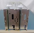
The Tektronix AM503A is a current probe amplifier plug-in for the TM500 system.
The AM503A and AM503B were updates to the original 1976 AM503. They have digital readout of deflection factor. The AM503S is an AM503A bundled with a TM502A mainframe, a TM-500 toolbox, and a A6302 probe.
The AM503, AM503A, AM503B, AM5030 and 11A16 use the same current probe input connector, an Amphenol 165-12 connector. It contains pins for hall element and transformer connections, lock detection, probe degaussing, and probe type encoding.
The AM503A and AM503B were designed by Mike Mende.
Key Specifications
| Bandwidth | |
|---|---|
| Sensitivity |
|
| Range |
|
| Output | Into 50 Ω Scope, Input Set to 10 mV/div |
| Power | 17 W |
| Compatible probes |
Links
Documents Referencing AM503A
- (no results)
Documents Referencing AM503B
- (no results)
Rear interface
The output can be detached from the front panel BNC socket which has a Peltola connector on the inside, and re-attached to a Peltola socket near the top of the interface connector, where it is terminated in 50 Ω and brought out on pin 28A (ground on 27A).
Pictures
AM503A
-
AM503A
AM503B
-
AM503B
-
Two AM503B in a TM502A
-
Rear View of Two AM503B Plug-Ins
-
PCB Component Side
-
PCB Soldering Side
-
Ceramic Daughter Board with Relays
-
2nd Daughter Board
-
Tek Specific IC
See also
- AM5030
- https://www.tek.com/datasheet/current-measurement-system-probes
- Current Probe Simulator 067-0802-99
Components
Some Parts Used in the AM503A
| Part | Part Number(s) | Class | Description | Used in |
|---|---|---|---|---|
| 165-2456-00 | 165-2456-00 | Hybrid integrated circuit | amplifier | AM503A • AM503B |
Some Parts Used in the AM503B
| Part | Part Number(s) | Class | Description | Used in |
|---|---|---|---|---|
| 165-2456-00 | 165-2456-00 | Hybrid integrated circuit | amplifier | AM503A • AM503B |


