Sampling oscilloscope
A sampling oscilloscope captures the time domain waveform at discrete time intervals using a sampling circuit. These captured voltages are then either stored in an analog fashion (integrator circuits and CRTs) or digitized and processed digitally. Through the 1960s, the sampling group at Tektronix was led by Al Zimmerman.
A distinction is made between real-time and equivalent time sampling. Real-time sampling requires a sampling rate of at least twice the highest signal bandwidth to capture the signal without aliasing artifacts. It is rare with analog oscilloscopes, but the method of choice for low to medium speed digital storage oscilloscopes, and allows for single shot waveform acquisition.
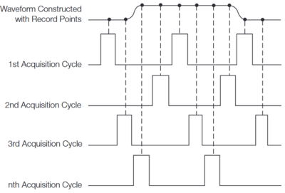
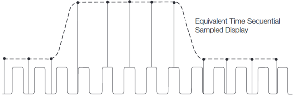
Equivalent time sampling requires repetitive signals but allows to capture a fast signal with a sampling rate much slower than the signal bandwidth. When talking about a "Sampling Oscilloscope" this approach is usually referred to. For digital instruments the term "Digital Sampling Oscilloscopes" is used. However the lines are blurry, since many instruments utilizing sampling concepts switch between different acquisition modes depending on the timebase setting.
Equivalent time sampling is further divided into sequential, and random sampling.
Instruments that have a random sampling mode usually also have a sequential sampling mode, e.g., the 7T11.
Scopes
Plug-ins
Reading
- Sampling Notes, Tektronix
- Sampling Oscilloscope Circuits, John Mulvey, Tektronix
- PSPL MTT 2003 paper: 100 GHz Sampler
- Construction of a Broadband Universal Sampling Head, J. R. Andrews and G. DeWitte
- Tektronix Sampling Instruments Brochure
- 50 Years of RF and Microwave Sampling, Mark Kahrs (2003)
- James R. Andrews, Comparison of Ultra-Fast Rise Sampling Oscilloscopes, Picosecond Pulse Labs Application Note 2a, 1989
- Sensitive Sampling Plug-ins Add New Capabilities, Cliff Moulton (OCR)
- February 1965 Service Scope: Sampling Concepts Reviewed
- Media:Cern 61-15 nanosecond sampling oscilloscope.pdf
- Transcript of "Sampling Oscilloscopes and Techniques" Training Film by Norm Winningstad (PDF)
- Introduction to Sampling Concepts (PDF)
- XYZs of Oscilloscopes (PDF)
- High-Speed Measurements Using Sampling Techniques (Student Workbook) (PDF)


