DAS9100: Difference between revisions
No edit summary |
No edit summary |
||
| Line 43: | Line 43: | ||
*02 [[GPIB]], [[RS-232]] interfaces and hardcopy output | *02 [[GPIB]], [[RS-232]] interfaces and hardcopy output | ||
*03 adds one extra +5 V power supply module, enables 6/8 slots to be populated with cards. | *03 adds one extra +5 V power supply module, enables 6/8 slots to be populated with cards. | ||
*04 adds two extra +5 V power supply | *04 adds two extra +5 V power supply modules, enables 8/8 slots to be populated with cards. | ||
*05 Rackmount hardware | *05 Rackmount hardware | ||
*06 [[GPIB]], two [[RS-232]] interfaces for master/slave operation and video output | *06 [[GPIB]], two [[RS-232]] interfaces for master/slave operation and video output | ||
Latest revision as of 05:51, 6 July 2024
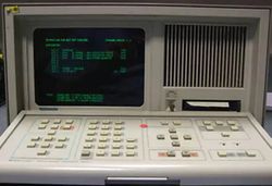
The Tektronix Digital Analysis 9100 is a logic analyzer system. It can have up to 104 acquisitions channels. Three different versions exist: The DAS9109 basic model, the DAS9129 color CRT model, and the DAS9119 model without screen intended for ATE use and remote control from another DAS9100 system.
It supports plug-in cards 91A04A, 91AE04A, 91A08, 91A32, 91A24, 91AE24, 91S16, 91S32, 91P16, 91P32, 91HS8, and 91HSE8.
The analyzers have an optional DC100 tape drive, used to store pattern generator menus, mnemonics menu and table, reference memory, and data acquisitions.
There is an also a software package, 91DVS, for IBM-compatible PCs.
See the Microprocessor support table for microprocessor disassembly configuration options.
Interfaces
- GPIB − The DAS9100 can operate via the GPIB port as either a talker or a listener. It is compatible with controllers such as the Tektronix 4041, 4051, 4052 and 4054.
- RS-232C − The RS232 interface has two modes of operation. The first mode is almost the same as the GPIB mode. The controller commands the analyzer to perform functions using the same commands as for GPIB. The hardware interface works with standard modems. The second mode is a Master-Slave operation. Using another 9100 you can remotely control another 9100.
- Composite output − The video out jack is part of option 02.
Key Specifications
- please add
Options
- 01 Adds a DC100 tape drive
- 02 GPIB, RS-232 interfaces and hardcopy output
- 03 adds one extra +5 V power supply module, enables 6/8 slots to be populated with cards.
- 04 adds two extra +5 V power supply modules, enables 8/8 slots to be populated with cards.
- 05 Rackmount hardware
- 06 GPIB, two RS-232 interfaces for master/slave operation and video output
Add-ons
See table for available cards

ROM images
- 160-0826-00 (U585)
- 160-0827-00 (U591)
- 160-0828-00 (U283)
- 160-0829-01 (U287)
- 160-0832-00 (U181)
- 160-0832-02 (U181)
- 160-0928-02 (U281)
- 160-0928-04 (U281)
- 160-0930-01 (U291)
- 160-0931-01 (U183)
- 160-0931-03 (U183)
- 160-0932-00 (U391)
- 160-1039-00 (U395)
- 160-1078-01 (U385)
- 160-1078-03 (U385)
- 160-1679-02 (U597)
- 160-1679-06 (U597)
- 160-1841-00 (U295)
- 160-2353-01
- 160-2354-01
I/O Option 2
- 160-0830-00 (A19U451) GPIB 1
- 160-1077-00 (A19U455) GPIB 2
- 160-1842-00 (A19U440, ≥B020000)
Links
Documents Referencing DAS9100
| Document | Class | Title | Authors | Year | Links |
|---|---|---|---|---|---|
| Tekscope 1981 V13 N3.pdf | Article | Configurable State-of-the Art Logic Analyzer Gives Choice of Performance | Bill Allen • John Huber | 1981 | DAS9100 • 91A32 • 91A08 • 91A04 • 91AE04 |
Pictures
-
DAS 9129 front
-
DAS 9129 Opt.06 rear
-
-
-
-
-
-
-
-
5V Supply Module (Opt03/04)
-
5V Supply Module (Opt03/04)
Components
Some Parts Used in the DAS9100
| Part | Part Number(s) | Class | Description | Used in |
|---|---|---|---|---|
| Zilog Z-80 | 156-0983-03 • 156-0983-04 • 156-0963-02 • 156-2280-00 | Monolithic integrated circuit | 8-bit microprocessor | 318 • 338 • 1503B • 1503C • 5223 • 834 • 835 • 836 • DAS9100 • SPG-271 • TSG-170 |


