S-52: Difference between revisions
No edit summary |
No edit summary |
||
| (10 intermediate revisions by 4 users not shown) | |||
| Line 1: | Line 1: | ||
{{Plugin Sidebar | {{Plugin Sidebar | ||
|manufacturer=Tektronix | |||
summary= | |series=7000 and 3S series sampling heads | ||
image=Tek-s52-front.jpg | | |type=S-52 | ||
caption=S-52 head, front panel | |summary=pulse generator | ||
|image=Tek-s52-front.jpg | |||
introduced=1971 | | |caption=S-52 head, front panel | ||
discontinued=1990 | | |introduced=1971 | ||
manuals= | |discontinued=1990 | ||
* [ | |designers=Murlan Kaufman | ||
* [ | |manuals= | ||
* [[Media:070-1101-01.pdf|Tektronix S-52 Instruction Manual, Revised Sep 1985]] | |||
* [[Media:070-1101-01 early.pdf|Tektronix S-52 Instruction Manual, Early Version]] | |||
}} | }} | ||
The '''Tektronix S-52''' is a pulse generator head compatible with S-series sampling units | The '''Tektronix S-52''' is a pulse generator head compatible with S-series sampling units | ||
like the [[3S2]], [[7S11]], and [[7S12]]. | like the [[3S2]], [[7S11]], and [[7S12]]. | ||
It was designed by [[Murlan Kaufman]]. | |||
It makes use of [[Patent US 3612910A|US Patent US3612910A, "Triggered Pulse Generator Having Automatic Bias Adjustment"]]. | |||
It puts out a 200 mV pulse into a load of 50 Ω. | It puts out a 200 mV pulse into a load of 50 Ω. | ||
| Line 19: | Line 22: | ||
The output is an [[SMA connector]]. | The output is an [[SMA connector]]. | ||
In addition to the main pulse output, | In addition to the main pulse output, the S-52 also produces a pre-trigger pulse 85 ns before the main pulse. | ||
the S-52 also produces a pre-trigger pulse 85 ns before the main pulse. | The delay is generated with a digital counter, and jitter between the pre-trigger pulse and the main pulse is specified as less than 10 ps. | ||
The delay is generated with a digital counter, | |||
and jitter between the pre-trigger pulse and the main pulse is specified as less than 10 ps. | |||
The pre-trigger pulse uses a [[BSM connector]]. | The pre-trigger pulse uses a [[BSM connector]]. | ||
| Line 28: | Line 29: | ||
{{Spec | Rise time | < 25 ps}} | {{Spec | Rise time | < 25 ps}} | ||
{{Spec | Output amplitude | 200 mV into 50 Ω (SMA)}} | {{Spec | Output amplitude | 200 mV into 50 Ω (SMA)}} | ||
{{Spec | Pulse Duration | > 350 ns}} | |||
{{Spec | Output impedance | 50 Ω «reverse terminated» (i.e. having controlled source impedance) }} | {{Spec | Output impedance | 50 Ω «reverse terminated» (i.e. having controlled source impedance) }} | ||
{{Spec | Pre-trigger output | 85 ns before main pulse (jitter < 10 ps), +1 V into 50 Ω (BSM) }} | {{Spec | Pre-trigger output | 85 ns before main pulse (jitter < 10 ps), +1 V into 50 Ω (BSM) }} | ||
| Line 44: | Line 46: | ||
and the output resistor may also provide some limited protection for the output tunnel diode. | and the output resistor may also provide some limited protection for the output tunnel diode. | ||
The S-52 uses a [[156-0048-00]] transistor array in the timing board. | The S-52 uses a [[156-0048-00]] (LM3046) transistor array in the timing board. | ||
==Links== | ==Links== | ||
* [http://www.amplifier.cd/Test_Equipment/Tektronix/Tektronix_7000_series_special/S-52.html Tek S-52 page @ amplifier.cd] | * [http://www.amplifier.cd/Test_Equipment/Tektronix/Tektronix_7000_series_special/S-52.html Tek S-52 page @ amplifier.cd] | ||
* [http://www.barrytech.com/tektronix/tek7000/teks52.html Tektronix S-52 @ barrytech.com] | * [http://www.barrytech.com/tektronix/tek7000/teks52.html Tektronix S-52 @ barrytech.com] | ||
{{Documents|Link=S-52}} | |||
{{PatentLinks|S-52}} | |||
==See Also== | ==See Also== | ||
Latest revision as of 11:54, 19 June 2024

The Tektronix S-52 is a pulse generator head compatible with S-series sampling units like the 3S2, 7S11, and 7S12. It was designed by Murlan Kaufman. It makes use of US Patent US3612910A, "Triggered Pulse Generator Having Automatic Bias Adjustment".
It puts out a 200 mV pulse into a load of 50 Ω. The pulse has a rise time of 25 ps or less. The output is an SMA connector.
In addition to the main pulse output, the S-52 also produces a pre-trigger pulse 85 ns before the main pulse. The delay is generated with a digital counter, and jitter between the pre-trigger pulse and the main pulse is specified as less than 10 ps. The pre-trigger pulse uses a BSM connector.
Key Specifications
| Rise time | < 25 ps |
|---|---|
| Output amplitude | 200 mV into 50 Ω (SMA) |
| Pulse Duration | > 350 ns |
| Output impedance | 50 Ω «reverse terminated» (i.e. having controlled source impedance) |
| Pre-trigger output | 85 ns before main pulse (jitter < 10 ps), +1 V into 50 Ω (BSM) |
Internals
The S-52 generates the main output pulse using a 50 mA low-capacitance tunnel diode with part number 153-0040-00.
The S-52 is similar to the S-50, but the S-50 has twice the pulse amplitude. The reason for this is that the S-52 has a 48 Ω resistor between the output tunnel diode and the output connector providing back termination, while the S-50 has no such resistor. Although the S-52 produces a smaller pulse, its output impedance is much better controlled than that of the S-50, and the output resistor may also provide some limited protection for the output tunnel diode.
The S-52 uses a 156-0048-00 (LM3046) transistor array in the timing board.
Links
Documents Referencing S-52
| Document | Class | Title | Authors | Year | Links |
|---|---|---|---|---|---|
| Rochester LLE Review Volume 25.pdf | Article | Computerized, Wide-Bandwidth, Multichannel, Soft X-Ray Diode Spectrometer for High Density Plasma Diagnosis | 1985 | 7S12 • S-52 • S-6 • LM7912 • LM7912A • 7912DPO | |
| RISOM2873.pdf | Article | Improvement of the Bandwidth of the Transient Digitizers in the LIDAR Thomson Scattering Diagnostic on JET | Erik Kristensen | 1990 | 7912AD • 7A29 • 7704A • 7S12 • S-6 • S-52 |
Patents that may apply to S-52
| Page | Title | Inventors | Filing date | Grant date | Links |
|---|---|---|---|---|---|
| Patent US 3612910A | Triggered pulse generator having automatic bias adjustment | Gene Cowan • George Frye | 1970-07-28 | 1971-10-12 | S-52 |
See Also
Pictures
-
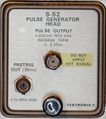
S-52 front
-
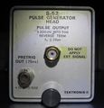
S-52 front A-prototype
-
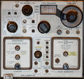
S-52 pulse generator and S-6 sampling head in a 7S12 TDR/Sampler plugin
-
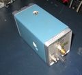
A-prototype of S-52


Internal
-
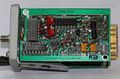
A1 Timing board (right)
-
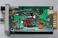
A3 Trigger board (left)
-
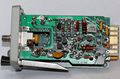
A2 Tunnel Diode Control board (center)
-
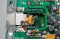
Tunnel diode mount
-
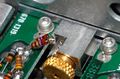
Tunnel diode mount, detail
-
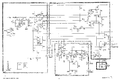
Schematic


Measurements
-
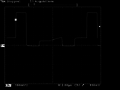
TDR "Self Portrait" — pulse reflected on S-6 "through" path (approx. 120 ps one way)
-
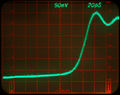
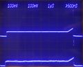
7S12 displaying the incident pulse from an S-52 (nom. < 25 ps) through an S-6 head (nom. < 30 ps). Displayed rise time ~35 ps confirms spec.
-
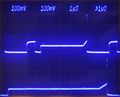
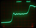
Full pulse pattern of a 7S12/S-52 in real time (top trace) and sampled (bottom trace) shown simultaneously on 7844. 7S12 trace at slowest possible sweep.
-
S-52 pulse in real time (top trace) and sampled (bottom trace) shown simultaneously on 7844. Approximately equal time scales.
-
Full pulse pattern of a S-52 (A-prototype) , driven by 3S6 (freerunning)


