S-2: Difference between revisions
No edit summary |
No edit summary |
||
| (19 intermediate revisions by 4 users not shown) | |||
| Line 1: | Line 1: | ||
{{Plugin Sidebar | {{Plugin Sidebar | ||
|manufacturer=Tektronix | |||
summary=Sampling Head | | |series=7000 and 3S series sampling heads | ||
image=Tek s2 front crop.jpg | | |type=S-2 | ||
caption=S-2 head | |summary=Sampling Head | ||
|image=Tek s2 front crop.jpg | |||
introduced=1967 | | |caption=S-2 head | ||
discontinued=1989 | | |introduced=1967 | ||
manuals= | |discontinued=1989 | ||
* [ | |designers= | ||
* [ | |manuals= | ||
* [[Media:070-0764-00.pdf|Tektronix S-2 Manual]] (OCR) | |||
* [[Media:Tek s-2 whole foldouts.pdf|Tektronix S-2 Manual Foldouts]] (whole, color) | |||
* [[Media:070-3012-00.pdf|Digital Measurement System S-2 Calibration]] | |||
}} | }} | ||
The '''Tektronix S-2 Sampling Head''' plug-in provides a single | The '''Tektronix S-2 Sampling Head''' plug-in provides a single [[GR-874 connector|GR-874]] 50 Ω input with a 75 ps risetime. | ||
[[GR-874 connector|GR-874]] 50 Ω input with a 75 ps risetime. | |||
The S-2 can be used in the 7000 series and 3S series of [[sampling oscilloscope|sampling plug-ins]]. | The S-2 can be used in the 7000 series and 3S series of [[sampling oscilloscope|sampling plug-ins]]. | ||
| Line 18: | Line 20: | ||
Noise is specified as less than 10 mV. | Noise is specified as less than 10 mV. | ||
When the S-2 was first introduced, the rise-time specification was 50 ps, but that | When the S-2 was first introduced, the rise-time specification was 50 ps, but that was not achieved in practice, so the rise-time specification was revised to be 75 ps. | ||
was not achieved in practice, so the rise-time specification was revised to be 75 ps. | |||
The interface between the GR-874 connector and the printed circuit board is described in US Patent 3,426,311. | The interface between the GR-874 connector and the printed circuit board is described in US Patent 3,426,311. | ||
{{BeginSpecs}} | {{BeginSpecs}} | ||
{{Spec | Rise time | 75 ps }} | {{Spec | Rise time | 75 ps (50 ps initially) }} | ||
{{Spec | Bandwidth | 4.66 GHz eq.}} | {{Spec | Bandwidth | 4.66 GHz eq.}} | ||
{{Spec | | {{Spec | Operating input voltage range | −1 V to +1 V with ≤1 V<sub>p-p</sub> signals }} | ||
{{Spec | Maximum single sample step | 200 mV}} | |||
{{Spec | Maximum input voltage | ±5 V<sub>DC</sub> or sine of 10 V<sub>p-p</sub> up to 10 MHz }} | |||
{{Spec | Input impedance | 50 Ω ±1% ([[GR-874]]) }} | |||
{{Spec | Noise | < 10 mV }} | |||
{{Spec | Features | trigger pickoff for internal triggering }} | |||
{{EndSpecs}} | {{EndSpecs}} | ||
==Links== | |||
{{Documents|Link=S-2}} | |||
{{PatentLinks|S-2}} | |||
==Similarity to [[S-1]]== | |||
The S-1 and S-2 samplers are constructed very similarly. The mechanical construction including internal connector locations is identical, and the preamp boards are almost identical. The main difference in these boards is the value of the gain adjust trimpot R46, which is 5k for the S-1 and 30k for the S-2, to allow higher gain settings to compensate for the shorter sampling pulses of the S-2. Bipolar transistors Q41 and Q45 are different types (why?). Preamp boards can be swapped between S-1s and S-2s for testing purposes without issues. | |||
The strobe boards use identical active components ([[avalanche transistor]] Q69 [[153-0556-00]] and [[Snap-off diode]] D61 152-0335-00), but the board layout is different to accommodate longer strobe clipping lines in the S-1. | |||
The sampling circuit itself is almost identical, except that the dampening resistors R7B and R8B of the [[S-1]] are missing in the S-2. The [[sampling diodes]] are different, the S-2 uses a 152-0361-00 GaAs matched pair. | |||
==Repair issues== | |||
* The input should always be terminated when not in use because the [[sampling diodes]] are easily damaged by excessive inputs or static discharge. See that article for possible replacements. | |||
* The ground contact of input termination resistor R4 can become intermittent, causing the input impedance to go high or fluctuating. The cure is to disassemble the sampler incuding the sampler board covers, and then carefully bend the ground tabs of the input termination resistor outward. | |||
==Prices== | |||
1979: $780 (~$3,000 in 2022 Dollars) | |||
According to an [[Media:Tek Schottky Diodes Memo rot.pdf|internal memo]], in 1979 annual sales were estimated at 321 units. | |||
==Pictures== | ==Pictures== | ||
| Line 33: | Line 60: | ||
<gallery> | <gallery> | ||
Tek s2 front.jpg | Tek s2 front.jpg | ||
S-52 s-2 rt.jpg | [[S-52]] and S-2 give 76 ps rise-time together | S-2_50ps_front.JPG | early S-2 with tr ≤ 50ps on front | ||
S2 schem1.png | schematic | S_2_old.JPG | early S-2 with overstickered tr ≤ 50ps | ||
S-2_eng_sample.JPG | two S-2 engineering sample (late model) | |||
S-52 s-2 rt.jpg | [[S-52]] and S-2 give 76 ps rise-time together | |||
S2 schem1.png | schematic | |||
Tek s2 strobe side.jpg | S-2 interior, strobe board side | Tek s2 strobe side.jpg | S-2 interior, strobe board side | ||
Tek s2 amp side.jpg | S-2 interior, amplifier board side | Tek s2 amp side.jpg | S-2 interior, amplifier board side | ||
Tek s2 bridge in place.jpg | Sampling diodes in place | Tek s2 bridge in place.jpg | Sampling diodes in place | ||
Tek s2 input term r4.jpg | Input termination resistor | Tek s2 input term r4.jpg | Input termination resistor R4 | ||
Tek s2 sampler r.jpg | Sampler board, right | Tek s2 sampler r.jpg | Sampler board, right | ||
Tek s2 sampler l.jpg | Sampler board, left | Tek s2 sampler l.jpg | Sampler board, left | ||
| Line 51: | Line 81: | ||
[[Category:7000 and 3S series sampling heads]] | [[Category:7000 and 3S series sampling heads]] | ||
[[Category:GR874]] | |||
Latest revision as of 10:58, 19 June 2024
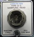
The Tektronix S-2 Sampling Head plug-in provides a single GR-874 50 Ω input with a 75 ps risetime.
The S-2 can be used in the 7000 series and 3S series of sampling plug-ins. It provides an internal trigger pickoff signal for internal triggering. Noise is specified as less than 10 mV.
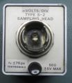
When the S-2 was first introduced, the rise-time specification was 50 ps, but that was not achieved in practice, so the rise-time specification was revised to be 75 ps.
The interface between the GR-874 connector and the printed circuit board is described in US Patent 3,426,311.
Key Specifications
| Rise time | 75 ps (50 ps initially) |
|---|---|
| Bandwidth | 4.66 GHz eq. |
| Operating input voltage range | −1 V to +1 V with ≤1 Vp-p signals |
| Maximum single sample step | 200 mV |
| Maximum input voltage | ±5 VDC or sine of 10 Vp-p up to 10 MHz |
| Input impedance | 50 Ω ±1% (GR-874) |
| Noise | < 10 mV |
| Features | trigger pickoff for internal triggering |
Links
Documents Referencing S-2
| Document | Class | Title | Authors | Year | Links |
|---|---|---|---|---|---|
| Service Scope 53 Dec 1968.pdf | Article | Digital Systems Come Of Age | John Bowne | 1968 | 3T5 • 3T6 • 3S5 • 3S6 • S-1 • S-2 • S-3 • S-4 • 568 • 230 |
| Service scope dec 1968 ocr.pdf | Article | Digital Systems Come of Age | John Bowne | 1968 | 3T5 • 3T6 • 3S5 • 3S6 • S-1 • S-2 • S-3 • S-4 • 568 • 230 • 240 • 241 • 250 |
| Service Scope 52 Oct 1968.pdf | Article | The State of the Art in Sampling | Al Zimmerman | 1968 | S-1 • S-2 • S-3 • S-4 • S-50 • S-51 • 285 • 3S1 • 3S2 • 3S5 • 3S6 • 3T2 • 3T5 • 3T6 • 3T77A • 568 • 230 |
| 42W-5850.pdf | Application Note | Preventing Sampling Head Overdrive and Static Damage | Gary Mott | 1985 | Sampling • S-1 • S-2 • S-3A • S-4 • S-5 • S-6 |
Similarity to S-1
The S-1 and S-2 samplers are constructed very similarly. The mechanical construction including internal connector locations is identical, and the preamp boards are almost identical. The main difference in these boards is the value of the gain adjust trimpot R46, which is 5k for the S-1 and 30k for the S-2, to allow higher gain settings to compensate for the shorter sampling pulses of the S-2. Bipolar transistors Q41 and Q45 are different types (why?). Preamp boards can be swapped between S-1s and S-2s for testing purposes without issues.
The strobe boards use identical active components (avalanche transistor Q69 153-0556-00 and Snap-off diode D61 152-0335-00), but the board layout is different to accommodate longer strobe clipping lines in the S-1.
The sampling circuit itself is almost identical, except that the dampening resistors R7B and R8B of the S-1 are missing in the S-2. The sampling diodes are different, the S-2 uses a 152-0361-00 GaAs matched pair.
Repair issues
- The input should always be terminated when not in use because the sampling diodes are easily damaged by excessive inputs or static discharge. See that article for possible replacements.
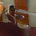
- The ground contact of input termination resistor R4 can become intermittent, causing the input impedance to go high or fluctuating. The cure is to disassemble the sampler incuding the sampler board covers, and then carefully bend the ground tabs of the input termination resistor outward.
Prices
1979: $780 (~$3,000 in 2022 Dollars)
According to an internal memo, in 1979 annual sales were estimated at 321 units.
Pictures
-
-
early S-2 with tr ≤ 50ps on front
-
early S-2 with overstickered tr ≤ 50ps
-
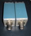
two S-2 engineering sample (late model)
-
S-52 and S-2 give 76 ps rise-time together
-
schematic
-
S-2 interior, strobe board side
-
S-2 interior, amplifier board side
-
Sampling diodes in place
-
Input termination resistor R4
-
Sampler board, right
-
Sampler board, left
-
Diode holder slides out
-
Sampler board underside
-
S-2 with amplifier board removed
-
Strobe board underside
-
S-2 with strobe board removed
-
S-2 pulse response


