P6042: Difference between revisions
No edit summary |
No edit summary |
||
| (2 intermediate revisions by 2 users not shown) | |||
| Line 11: | Line 11: | ||
|manuals= | |manuals= | ||
* [[Media:070-0629-00.pdf|Tektronix P6042 Manual]] | * [[Media:070-0629-00.pdf|Tektronix P6042 Manual]] | ||
* [[Media:Tek p6042 calibration procedure dec 1967.pdf|Tektronix P6042 Calibration Procedure]] | |||
}} | }} | ||
The '''Tektronix P6042''' is a DC to 50 MHz current probe [[introduced in 1967]]. It was designed by [[Cal Hongel]]. | The '''Tektronix P6042''' is a DC to 50 MHz current probe [[introduced in 1967]]. It was designed by [[Cal Hongel]]. | ||
| Line 46: | Line 47: | ||
* [https://www.pa4tim.nl/?p=3135 P6042 repair by Fred, PA4TIM] | * [https://www.pa4tim.nl/?p=3135 P6042 repair by Fred, PA4TIM] | ||
* [https://www.eetimes.com/author.asp?section_id=36&doc_id=1330593 P6042 teardown @ EEtimes] | * [https://www.eetimes.com/author.asp?section_id=36&doc_id=1330593 P6042 teardown @ EEtimes] | ||
{{Documents|Link=P6042}} | |||
{{PatentLinks|P6042}} | |||
==Pictures== | ==Pictures== | ||
Latest revision as of 04:40, 13 July 2024
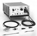
The Tektronix P6042 is a DC to 50 MHz current probe introduced in 1967. It was designed by Cal Hongel.
The sensor contains a current transformer for HF and a hall effect sensor for LF/DC components. The amplifier combines DC/LF and HF signals.
The AM503, introduced about a decade later, is a redesign of the P6042 with removable probes.
Key Specifications
| Bandwidth | DC to 50 MHz (−3 dB) |
|---|---|
| Rise time | 7 ns |
| Ranges | 1 mA/div to 1 A/div (1–2–5) with scope in 50 mV/div |
| Output | to 50 Ω scope input at 50 mV/div |
| Maximum input | 10 A DC+peak AC in 5 mA to 1 A ranges, 0.5 A in 1 mA and 2 mA ranges |
| Power | 90-136 or 180-272 V, 20 W |
Internals
Locking the probe requires pushing past the resistance felt when the core almost closes. This engages a mechanism that firmly presses both core halves together, and extinguishes the "Probe unlocked" indicator.
The P6042's core halves are precision lapped and potted with epoxy. They have Mu-metal screening. The lower (fixed) core also contains the Hall element. Unfortunately, the P6042 probe is quite sensitive mechanically, and in many units offered for sale, the cores are damaged.
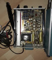
The amplifier front-end is constructed using a 156-0014-00 differential amplifier integrated circuit, labelled "M18", which cross-references to a long-obsolete Teledyne "831-BE". Jim Williams' Applicaion Note 61 contains a replacement circuit using LT1228 opamps (page 19).
Prices
- $525 in 1967 (~$5,500 in 2022 Dollars)
Links
- Service Scope 46, October 1967
- Tek P6042 page @ amplifier.cd
- Tek P6042 page @ barrytech.com
- Tek P6042 page @ radiomuseum.org
- P6042 repair by Fred, PA4TIM
- P6042 teardown @ EEtimes
Documents Referencing P6042
| Document | Class | Title | Authors | Year | Links |
|---|---|---|---|---|---|
| Tekscope 1974 V6 N3.pdf | Article | Using your oscilloscope probe (Part 2) | Riley Stock | 1974 | P6201 • P6042 |
Patents that may apply to P6042
| Page | Title | Inventors | Filing date | Grant date | Links |
|---|---|---|---|---|---|
| Patent US 3482163A | Magnetic signal measuring device including degaussing means | Bill Peek • Eldon Lee Hoven | 1967-05-24 | 1969-12-02 | P6042 • A6302 • A6302XL • A6303 • A6303XL • A6304XL • A6312 • AM503 • AM503A • AM503B • AM5030 • 11A16 |
Pictures
-
amplifier front
-
amplifier and sensor
-
sensor detail
-
rear view
-
catalog image
-
P6042 amplifier internal view
-
P6042 amplifier internal view
-
P6042 amplifier internal view
-
Top half core of probe
-
Bottom of probe with half core and Hall sensor


