7A21N: Difference between revisions
No edit summary |
No edit summary |
||
| (One intermediate revision by the same user not shown) | |||
| Line 10: | Line 10: | ||
|designers= | |designers= | ||
|manuals= | |manuals= | ||
* [[Media:070-1367-00.pdf|Tektronix 7A21N Manual]] | * [[Media:070-1367-00.pdf|Tektronix 7A21N Manual]] | ||
* [[Media:070-1962-00.pdf|Tektronix 7A21N Manual]] (SN B040000-up | * [[Media:070-1962-00.pdf|Tektronix 7A21N Manual]] (SN B040000-up) | ||
}} | }} | ||
The '''Tektronix 7A21N''' is a 7000-series plug-in that provides direct access to the CRT for fast-risetime | The '''Tektronix 7A21N''' is a 7000-series plug-in that provides direct access to the CRT for fast-risetime AC signals on the 500 MHz-class 7900 series scopes, i.e. [[7904]]/[[7904A]], [[R7903]], [[7934]], [[R7912]]. | ||
Input signals are applied via a pair of [[GR-874]] connectors. | Input signals are applied via a pair of [[GR-874]] connectors. | ||
The 7A21N is fully passive | The 7A21N is fully passive. It can be wired for single-ended or differential signals internally. | ||
It includes two delay lines, two inverting "transformers" and a passive bridge and power divider. | It includes two delay lines, two inverting "transformers", and a passive bridge and power divider. | ||
There is no trigger pick-off, | There is no trigger pick-off, i.e. the trigger signal will have to be provided externally, e.g. through a [[7M11]]. | ||
The 7A21N is intended to be installed in the Left Vertical bay of the 79xx mainframe and requires the mainframe's vertical amplifier board to be replaced with the 7A21N CRT Input Network and 7A21N CRT Termination boards, which are shipped plugged into the back side of the 7A21N circuit board. (A second-hand 7A21 without these boards and associated cables is useless!) | The 7A21N is intended to be installed in the Left Vertical bay of the 79xx mainframe and requires the mainframe's vertical amplifier board to be replaced with the 7A21N CRT Input Network and 7A21N CRT Termination boards, which are shipped plugged into the back side of the 7A21N circuit board. (A second-hand 7A21 without these boards and associated cables is useless!) | ||
| Line 26: | Line 26: | ||
{{BeginSpecs}} | {{BeginSpecs}} | ||
{{Spec | Deflection | {{Spec | Deflection | < 4 V/Div (SE), < 2 V/Div (Differential) }} | ||
{{Spec | Bandwidth | 20 kHz – 1 GHz }} | {{Spec | Bandwidth | 20 kHz – 1 GHz }} | ||
{{Spec | Input impedance | 50 Ω }} | {{Spec | Input impedance | 50 Ω }} | ||
| Line 33: | Line 33: | ||
==Links== | ==Links== | ||
{{Documents|Link=7A21N}} | |||
{{PatentLinks|7A21N}} | |||
==Pictures== | ==Pictures== | ||
<gallery> | <gallery> | ||
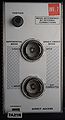
Tek 7a21n front.jpg|7A21N front | |||
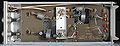
7a21 right.jpg|7A21N right | |||
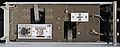
Tek 7a21 left.jpg|7A21N left (including vertical amp replacement boards) | |||
Tek_7a21_rear_conn.jpg|7A21N rear | |||
7a21n-accessories-manual.jpg | Standard accessories | |||
</gallery> | </gallery> | ||
Latest revision as of 06:27, 11 September 2024

The Tektronix 7A21N is a 7000-series plug-in that provides direct access to the CRT for fast-risetime AC signals on the 500 MHz-class 7900 series scopes, i.e. 7904/7904A, R7903, 7934, R7912.
Input signals are applied via a pair of GR-874 connectors.
The 7A21N is fully passive. It can be wired for single-ended or differential signals internally. It includes two delay lines, two inverting "transformers", and a passive bridge and power divider. There is no trigger pick-off, i.e. the trigger signal will have to be provided externally, e.g. through a 7M11.
The 7A21N is intended to be installed in the Left Vertical bay of the 79xx mainframe and requires the mainframe's vertical amplifier board to be replaced with the 7A21N CRT Input Network and 7A21N CRT Termination boards, which are shipped plugged into the back side of the 7A21N circuit board. (A second-hand 7A21 without these boards and associated cables is useless!)
Obviously, installing the replacement boards also disables the mainframe's readout facility and second vertical plug-in bay.
Key Specifications
| Deflection | < 4 V/Div (SE), < 2 V/Div (Differential) |
|---|---|
| Bandwidth | 20 kHz – 1 GHz |
| Input impedance | 50 Ω |
| Max. input | 6 W avg @ 50 Ω, 200 V DC |
Links
Documents Referencing 7A21N
| Document | Class | Title | Authors | Year | Links |
|---|---|---|---|---|---|
| 7000 series brochure March 1973.pdf | Brochure | 7000 series brochure, March 1973 | 1973 | 7A11 • 7A12 • 7A13 • 7A14 • 7A15A • 7A16A • 7A17 • 7A18 • 7A19 • 7A21N • 7A22 • 7B50 • 7B53A • 7B70 • 7B71 • 7B92 • 7CT1N • 7D11 • 7D13 • 7D14 • 7D15 • 7M11 • 7L12 • 7S11 • 7S12 • 7T11 • 7704A • R7704 • 7904 • R7903 • 7603 • R7603 • 7403N • R7403N • 7313 • R7313 • 7613 • R7613 • 7623 • R7623 • P7001 |
Pictures
-
7A21N front
-
7A21N right
-
7A21N left (including vertical amp replacement boards)
-
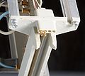
7A21N rear
-
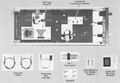
Standard accessories


Precursor/prototype to the 7A21N:

