122: Difference between revisions
No edit summary |
No edit summary |
||
| (16 intermediate revisions by 2 users not shown) | |||
| Line 1: | Line 1: | ||
{{Instrument Sidebar | |||
|manufacturer=Tektronix | |||
|model=122 | |||
|class=Amplifier | |||
|series= | |||
|summary=low-level preamplifier | |||
|image=Tek 122 x.jpg | |||
|caption=Tek 122 early model | |||
|introduced=1950 | |||
|discontinued=(?) | |||
|designers= | |||
|manuals= | |||
* [[Media:070-246.pdf|Tektronix 122 and 125 Manual]] | |||
* [https://w140.com/brophy_122_mod.pdf Low Noise Modifications of the 122] | |||
}} | |||
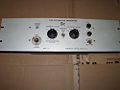
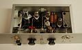
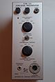
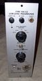
The '''Tektronix 122''' is an external low-frequency low-level preamplifier. | |||
The | The low-frequency cutoff and high frequency cutoff can be selected. 40 kHz is the highest cutoff. | ||
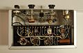
The input is differential, using an [[XLR connector]]. The output is through a [[UHF connector|UHF (SO-239) connector]], single-ended. | |||
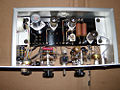
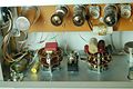
The amplifier electronics are on a plastic board with metal studs where components are soldered in place. | |||
The board is mechanically isolated from the case by four rubber bushings. The 122 is the only Tektronix product ever made that has a rotary two position power switch. | |||
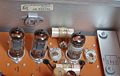
The 122 has four stages of amplification. | |||
The first stage is a direct-coupled differential amplifier formed by both halves if a [[12AX7]] dual-triode tube. | |||
The total plate current of the input stage is about 450 μA. | |||
The second stage is a [[12AU7]] differential amplifier, differentially driven by the first stage. | |||
There are DC blocking capacitors between plates of the first stage and the grids of the second stage. | |||
The second stage is coupled to the third stage by capacitors, which can be switched to select the low-frequency cutoff frequency. | |||
The third stage is a common-cathode amplifier formed from one half of a 12AU7 dual triode tube. | |||
The plate load resistors of the third stage amplifier are shunted by switchable capacitors, allowing the high-frequency cutoff to be selected. | |||
The resulting signal is buffered by a cathode-follower stage formed from the other triode in the third stage's 12AU7 tube, biased at 1.8 mA plate current. | |||
The output impedance is rated to be about 1000 Ω. | |||
For low noise performance and freedom from oscillations, the power supplies in the 122 are carefully bypassed. | |||
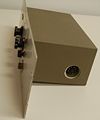
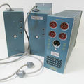
The B+ supply of +135 V<sub>DC</sub> (along with -90 V<sub>DC</sub> and -6 V<sub>DC</sub>) | |||
comes into the 122 through an [[octal connector]], typically from a Type [[125]] power supply. | |||
(Note: The [[160]] power supply is not compatible. The voltages are quite different.) | |||
The raw voltage coming in is used for the plate supply of the output (fourth) stage. | |||
That voltage is low-pass filtered to produce voltage "C" which is used as the plate supply for the third stage. | |||
Voltage "C" is low-pass filtered to produce voltage "B", the plate supply for the second stage. | |||
Finally, voltage "B" is low-pass filtered to produce voltage "A", the plate supply for the first stage. | |||
The result is that the sensitive first and second stages have well filtered plate supplies. | |||
This technique is also seen in other gear from the era, such as the McIntosh MC-30 audio power amplifier. | |||
The power requirements of the 122 are: | |||
* +135 V at 5 mA | |||
* -90 V at 4 mA | |||
* 6.3 V at 900 mA | |||
The 122 appears in three form factors: | |||
* 122 (standard, vertical orientation, no mounting ears) | |||
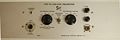
* RM122 (rack mount, horizontal orientation, with wide front panel for mounting mounting in a standard 19" rack, later called "R122") | |||
* FM122 (frame mount, vertical orientation, for use in the [[014-002]] mounting frame, later called "F122") | |||
==Pictures== | |||
<gallery> | <gallery> | ||
Tek 122 x.jpg|early model | |||
Tek 122 x2.jpg|early model | |||
Tek 122 front.jpg|early model | |||
Tek 122 power.jpg|early model | |||
Tek 122 front close.jpg|early model | |||
Tek 122 bottom inside.jpg|early model | |||
Tek 122 top inside.jpg|early model | |||
Tek 122 schem.png | schematic | |||
Tek 122 int right.jpg|late model | |||
Tek 122 int panel.jpg|late model | |||
Tek 122 late int left.jpg|late model | |||
Tek 122 late front.jpg|late model | |||
Tek 122 system rs 1.jpg | |||
Tek 122 system rs 2.jpg | |||
Tek fm122 front.jpg|Tek FM122 front | |||
Tek fm122 top connector.jpg|Tek FM122 top power connector | |||
</gallery> | </gallery> | ||
==Components== | |||
{{Parts|122}} | |||
[[Category:Amplifiers]] | |||
Latest revision as of 11:15, 21 September 2023

The Tektronix 122 is an external low-frequency low-level preamplifier.
The low-frequency cutoff and high frequency cutoff can be selected. 40 kHz is the highest cutoff. The input is differential, using an XLR connector. The output is through a UHF (SO-239) connector, single-ended. The amplifier electronics are on a plastic board with metal studs where components are soldered in place. The board is mechanically isolated from the case by four rubber bushings. The 122 is the only Tektronix product ever made that has a rotary two position power switch.
The 122 has four stages of amplification. The first stage is a direct-coupled differential amplifier formed by both halves if a 12AX7 dual-triode tube. The total plate current of the input stage is about 450 μA.
The second stage is a 12AU7 differential amplifier, differentially driven by the first stage. There are DC blocking capacitors between plates of the first stage and the grids of the second stage. The second stage is coupled to the third stage by capacitors, which can be switched to select the low-frequency cutoff frequency. The third stage is a common-cathode amplifier formed from one half of a 12AU7 dual triode tube. The plate load resistors of the third stage amplifier are shunted by switchable capacitors, allowing the high-frequency cutoff to be selected. The resulting signal is buffered by a cathode-follower stage formed from the other triode in the third stage's 12AU7 tube, biased at 1.8 mA plate current. The output impedance is rated to be about 1000 Ω.
For low noise performance and freedom from oscillations, the power supplies in the 122 are carefully bypassed. The B+ supply of +135 VDC (along with -90 VDC and -6 VDC) comes into the 122 through an octal connector, typically from a Type 125 power supply. (Note: The 160 power supply is not compatible. The voltages are quite different.) The raw voltage coming in is used for the plate supply of the output (fourth) stage. That voltage is low-pass filtered to produce voltage "C" which is used as the plate supply for the third stage. Voltage "C" is low-pass filtered to produce voltage "B", the plate supply for the second stage. Finally, voltage "B" is low-pass filtered to produce voltage "A", the plate supply for the first stage. The result is that the sensitive first and second stages have well filtered plate supplies. This technique is also seen in other gear from the era, such as the McIntosh MC-30 audio power amplifier.
The power requirements of the 122 are:
- +135 V at 5 mA
- -90 V at 4 mA
- 6.3 V at 900 mA
The 122 appears in three form factors:
- 122 (standard, vertical orientation, no mounting ears)
- RM122 (rack mount, horizontal orientation, with wide front panel for mounting mounting in a standard 19" rack, later called "R122")
- FM122 (frame mount, vertical orientation, for use in the 014-002 mounting frame, later called "F122")
Pictures
-
early model
-
early model
-

early model
-
early model
-
early model
-
early model
-
early model
-
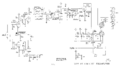
schematic
-
late model
-
late model
-

late model
-
late model
-

-
-
Tek FM122 front
-

Tek FM122 top power connector


Components
Some Parts Used in the 122
| Part | Part Number(s) | Class | Description | Used in |
|---|---|---|---|---|
| 12AU7 | 154-041 • 154-0041-00 • 154-0287-00 | Vacuum Tube (Dual Triode) | dual medium-μ triode | 104 • 104A • 122 • 160 • 161 • 162 • 181 • 190 • 310 • 310A • 316 • 317 • 3C66 • 502 • 502A • 507 • 511A • 512 • 516 • 517 • 517A • 524 • 526 • 535 • 536 • 545 • 545A • 545B • 547 • 549 • 555 • 561 • 564 • 570 • 575 • 581 • 581A • 585 • 585A • C • D • E • N • Q • Hickok 1825 |