502

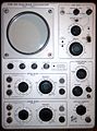
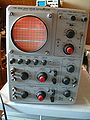
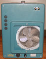
The Tektronix 502 is a dual-beam oscilloscope introduced in 1958, followed by the 502A in 1963. There is also a rack-mount model, the RM502A.
Both beams have differential inputs. The horizontal deflection plates are common to both beams.
The vertical signal path of the 502 was designed by Rodgers Jenkins.
Mod 104 on a 502 provides single sweep lockout. This feature is standard on the 502A, which also has beam finder switches for each channel.
A recessed switch in the left side panel allows the upper beam amplifier to be connected to the horizontal deflection plates for single-beam X-Y operation, providing a differential X input with the same sensitivity as the Y channel. The upper beam is positioned off screen in this mode.
If the combination of time base setting and magnification selector results in a sweep faster than 1 μs/div, the horizontal scale is not calibrated, and a lamp on the front panel lights up to remind the operator of that.
Key Specifications
| Deflection | 100 μV/cm to 20 V/cm, 1−2−5, ±3% |
|---|---|
| Bandwidth | 1 MHz @ 200 mV/cm and above; 400 kHz @ 50 mV/cm, 200 kHz @ 5 mV/cm, 100 kHz @ 200 μV/cm |
| CMRR | 502A: 40,000:1 @ 100 mV/cm and 1 kHz |
| Input impedance | 1 MΩ // 47 pF |
| Sweep | 1 μs/cm to 5 s/cm, 1−2−5, ±3%; magnifier ×2, ×5, ×10 or ×20 |
| CRT | Early 502: Type T60P2/T502P2/T5020P2; Late 502, 502A: Type T5021P2; (P1, P7 or P11 were available as options) 10 vertical and 10 horizontal 1 cm divisions 3 kV acceleration |
| Dimensions | 597 mm (23½") × 286 mm (11¼") × 381 mm (15") L×W×H |
| Weight | 23.6 kg (52lb) |
Links
Documents Referencing 502
- (no results)
Documents Referencing 502A
| Document | Class | Title | Authors | Year | Links |
|---|---|---|---|---|---|
| Service Scope 42 Feb 1967.pdf | Article | Simplify Waveform Measurements | 1967 | 502A |
- Tektronix 502A @ amplifier.cd (many internal pictures)
- Tektronix 502A internals @ youtube (German)
Prices
| Year | 1959 | 1961 | 1963 (A) | 1971 (A) |
|---|---|---|---|---|
| Catalog price | $825 | $825 | $1,050 | $1,265 |
| In 2023 Dollars | $8,700 | $8,500 | $10,500 | $9,600 |
Internals
The −150 V supply uses a 5651 voltage reference tube as its reference.
The 6.2 VDC heater supply for the tubes in the first stage differential amplifier is transistor-regulated. This heater supply uses the −150 V supply as its reference.
There is no post-deflection acceleration. The CRT cathode voltage is −2.9 kV.
The early 502 uses a single supply for the upper beam and lower beam CRT cathodes (HV transformer 120-114). Later models (1959+, see 070-090) and the 502A have separate supplies for the two CRT cathodes (HV transformer 120-150). This improvement allows slight differences in horizontal CRT sensitivity between the two beams to be cancelled out in step 8 of the calibration procedure.
Later 502A models have a solid state (plus nuvistor) input stage, a 6DJ8 as the deflection amplifier, and transistors as amplifiers and emitter followers (only in the newest version).
The 502 has a 123 °F (50.5 °C) thermal cutoff switch.
Pictures
502
-

502 with (single-beam) X-Y display
-
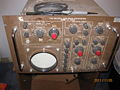
502 Mod.104 (single sweep), front
-

502 Mod.104 (single sweep), front from lower left
-
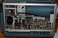
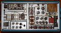
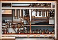
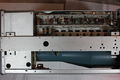
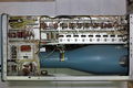
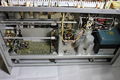
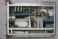
502 left interior
-
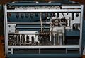
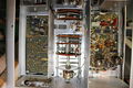
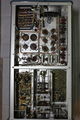
502 right interior
-
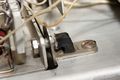
rubber shock mount of amplifier sub-chassis
-
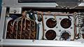
502 bottom
-
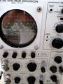
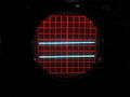
502 trace
-
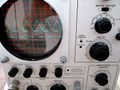
502 trace
-
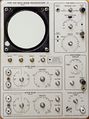
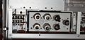
502 front panel without knobs
-
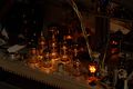
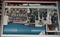
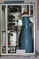
502 power supply section in operation


502A
-
502A
-

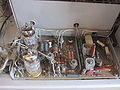
502A right internal
-
502A right
-
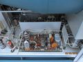
502A left
-
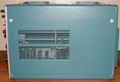
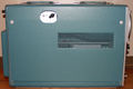
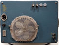
502A rear
-
Solid-state input stage with two 6DJ*
-
502A vertical amp sn 25,997 to 30,999


RM502A
-
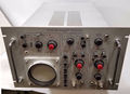
RM502A
-
RM502A rear
-
RM 502A
-
RM 502A display
-
RM 502A bottom
-
RM 502A transformer wiring
-
RM 502A top
-
RM 502A vibration-isolated vertical amp


Third version 502A, serial number ≥31,000
-
top side lower beam input amp and attenuator, bottom side of upper beam vert input board
-
late model RM502A
-
late model RM502A
-
late model RM502A
-
late model RM502A
-

late model RM502A
-
late model RM502A
-
late model RM502A


Diagrams
-
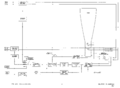
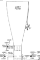
502A block diagram
-
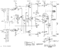
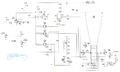
502A vertical amplifier
-
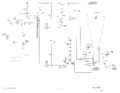
Early 502 CRT circuit, 120-114 transformer (secondary transformer pin numbers incorrect)
-
Later 502 CRT circuit, 120-150 transformer
-
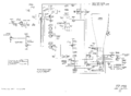
502A CRT circuit, 120-150 transformer
-
Cartoon in schematic: Mountain Climber


Applications
-
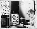
Tek 502A in a Physiology lab

Components
Some Parts Used in the 502