517: Difference between revisions
No edit summary |
No edit summary |
||
| Line 1: | Line 1: | ||
{{Oscilloscope Sidebar |manufacturer=Tektronix | | {{Oscilloscope Sidebar | ||
|manufacturer=Tektronix | |||
model= 517 | | |series= | ||
summary=50 MHz scope | | |model=517 | ||
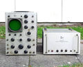
image=Tek 517 vt.jpg| | |summary=50 MHz scope | ||
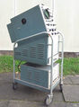
caption= Tektronix 517 at VintageTek Museum | | |image=Tek 517 vt.jpg | ||
introduced=1951 | | |caption=Tektronix 517 at VintageTek Museum | ||
discontinued=1965 | | |introduced=1951 | ||
manuals= | |discontinued=1965 | ||
* [ | |designers=Logan Belleville;Dick Rhiger | ||
|manuals= | |||
* [[Media:IM-517.pdf|Early 517 Manual (IM-517)]] (PDF, OCR) | |||
* [ | * [[Media:070-229.pdf|Later Manual (070-229) Covering the 517 and 517A]] (PDF, OCR) | ||
* [[Media:Tek_517_calibration_guide.pdf|Tektronix 517 Calibration Guide]] (PDF, OCR) | |||
* [[Media: | |||
}} | }} | ||
The '''Tektronix 517''' is a 50 MHz scope [[introduced in 1950]] or [[introduced in 1951|1951]]. | The '''Tektronix 517''' is a 50 MHz scope [[introduced in 1950]] or [[introduced in 1951|1951]]. | ||
The power supply is an external box, like the [[507]], [[551]] and [[555]]. | The power supply is an external box, like the [[507]], [[551]] and [[555]]. | ||
The 517 does not take plug-ins. | The 517 does not take plug-ins. There is also a 517A (1955-1965). | ||
There is also a 517A (1955-1965). | |||
==Specifications== | ==Specifications== | ||
The power consumption of a 517 is 1250 watts. | The power consumption of a 517 is 1250 watts. | ||
The indicator unit weighs 76 pounds and the external | The indicator unit weighs 76 pounds and the external power supply weighs 72 pounds. | ||
power supply weighs 72 pounds. | |||
=== Historic Context === | === Historic Context === | ||
The 517 closely resembles a scope that Tektronix developed under a contract | The 517 closely resembles a scope that Tektronix developed under a contract for the US military during 1949 and 1950. (See link below.) | ||
for the US military during 1949 and 1950. (See link below.) | |||
Tektronix engineer [[Frank Hood]] recollects: | Tektronix engineer [[Frank Hood]] recollects: | ||
<blockquote> | <blockquote> | ||
"A lot of progress was made in 1949 and 1950. | "A lot of progress was made in 1949 and 1950. | ||
Work was well underway by [[Logan Belleville]], [[Dick Rhiger]] and [[Howard Vollum|Howard]] | Work was well underway by [[Logan Belleville]], [[Dick Rhiger]] and [[Howard Vollum|Howard]] on the high speed scope, the 517. | ||
on the high speed scope, the 517. | |||
This used some brand new circuitry, [[distributed amplifier|distributed (or chain) amplifiers]], | This used some brand new circuitry, [[distributed amplifier|distributed (or chain) amplifiers]], using 16 to 20 tubes in each stage to get the power needed to handle the high frequencies. | ||
using 16 to 20 tubes in each stage to get the power needed to handle the high frequencies. | |||
Our best prediction at that time was that there were only about 30 to 50 people in the whole world | Our best prediction at that time was that there were only about 30 to 50 people in the whole world who had need of a scope with 60 to 100 megacycle bandwidth. | ||
who had need of a scope with 60 to 100 megacycle bandwidth. | As it turned out, when we brought out a higher speed scope, people were able to design equipment of greater bandwidth and needed even faster measuring instruments. | ||
As it turned out, when we brought out a higher speed scope, | The cycle was regenerative. Having faster, more accurate measuring tools created a demand for even more measuring tools. | ||
people were able to design equipment of greater bandwidth and needed even faster measuring instruments. | |||
The cycle was regenerative. | |||
Having faster, more accurate measuring tools created a demand for even more measuring tools. | |||
We eventually sold several thousand of this instrument." | We eventually sold several thousand of this instrument." | ||
</blockquote> | </blockquote> | ||
| Line 48: | Line 41: | ||
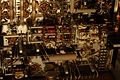
==Internals== | ==Internals== | ||
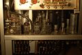
=== External Power Supply === | === External Power Supply === | ||
The external power supply and oscilloscope are connected by a removable cable | The external power supply and oscilloscope are connected by a removable cable with a Jones plug on one end and a Jones socket on the other end. | ||
with a Jones plug on one end and a Jones socket on the other end. | Units with serial numbers from 101 through 1739 use 12-pin Jones 2412 connectors; after that it is a 16-pin Jones connector. | ||
Units with serial numbers from 101 through 1739 use 12-pin Jones 2412 connectors; | ''(Was a 16-pin Jones connector used or did they go directory from the 12-pin Jones connector to the 16-pin Amphenol power connector used by the [[555]]?)'' | ||
after that it is a 16-pin Jones connector. | |||
''(Was a 16-pin Jones connector used or did they go directory from the 12-pin Jones connector | |||
to the 16-pin Amphenol power connector used by the [[555]]?)'' | |||
The voltages on the 12-pin connector are: | The voltages on the 12-pin connector are: | ||
| Line 67: | Line 57: | ||
Later 517A units uses the same cable as the [[551]] and [[555]]. | Later 517A units uses the same cable as the [[551]] and [[555]]. | ||
Although they use the same cable, they are completely incompatible | Although they use the same cable, they are completely incompatible – the voltages are different. | ||
The 517's external power supply provides +750 V to the indicator unit. | |||
provides +750 V to the indicator unit. The highest voltage provided by | The highest voltage provided by the 555 and 551 power supplies is +500 V. | ||
the 555 and 551 power supplies is + | Also, for example, the 517A has +180 V on pin 8 of the 16-pin connector while the 555 and 551 have -150 V on pin 8. | ||
has +180 V on pin 8 of the 16-pin connector while the 555 and 551 have | |||
-150 V on pin 8. | |||
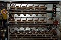
=== Distributed Amplifiers === | === Distributed Amplifiers === | ||
The 517 makes extensive use of the [[distributed amplifier]] concept. | The 517 makes extensive use of the [[distributed amplifier]] concept. | ||
Originally the [[5XP]] CRT was used, | Originally the [[5XP]] CRT was used, which has 38 V/cm vertical deflection sensitivity when operated with 24 kV acceleration voltage. | ||
which has 38 V/cm vertical deflection sensitivity when operated with 24 kV acceleration voltage. | |||
''(Is this correct? It doesn't agree with the 5XP datasheet.)'' | ''(Is this correct? It doesn't agree with the 5XP datasheet.)'' | ||
Since the vertical sensitivity at the input connector is 0.1 V/cm, we can calculate that | Since the vertical sensitivity at the input connector is 0.1 V/cm, we can calculate that the voltage gain from the input connector to the vertical deflection plates is 380. | ||
the voltage gain from the input connector to the vertical deflection plates is 380. | For 4 cm deflection, a 152 V differential output swing is required. There are DC blocking capacitors at various places in the signal path. | ||
For 4 cm deflection, a 152 V differential output swing is required. There are DC blocking | The slowest sweep is 20 μs/cm. The 517 is not designed for low-frequency use. | ||
capacitors at various places in the signal path. The slowest sweep is 20 μs/cm. The 517 is | |||
not designed for low-frequency use. | |||
The vertical signal path is as follows: | The vertical signal path is as follows: | ||
| Line 98: | Line 83: | ||
* Gain Stage 5: differential, twelve sections, distributed, [[6CB6]] pentodes | * Gain Stage 5: differential, twelve sections, distributed, [[6CB6]] pentodes | ||
There is a trigger amplifier in the 517 which can take its input from | There is a trigger amplifier in the 517 which can take its input from an external source, or from the trigger pickoff in the vertical pre-amp, or from the internal rate generator circuit. | ||
an external source, or from the trigger pickoff in the vertical pre-amp, or | The trigger amplifier circuit has five stages: | ||
from the internal rate generator circuit. The trigger amplifier circuit has | |||
five stages: | |||
* Phase Splitter: [[6J6]] dual-triode connected as a differential amplifier | * Phase Splitter: [[6J6]] dual-triode connected as a differential amplifier | ||
| Line 112: | Line 95: | ||
The 517 uses 24 kV total acceleration voltage on the CRT. | The 517 uses 24 kV total acceleration voltage on the CRT. | ||
This is generated by the [[420|Type 420]] High Voltage Power Supply subsystem in the 517. | This is generated by the [[420|Type 420]] High Voltage Power Supply subsystem in the 517. | ||
It uses a 1.8 kHz oscillator to produce the high voltage, | It uses a 1.8 kHz oscillator to produce the high voltage, unlike other Tek scopes which use HV oscillators in the ultrasonic range. | ||
unlike other Tek scopes which use HV oscillators in the ultrasonic range. | |||
The 517 has a switch on the front panel that selects between normal vertical sensitivity, | The 517 has a switch on the front panel that selects between normal vertical sensitivity, which uses the full 24 kV acceleration voltage, | ||
which uses the full 24 kV acceleration voltage, | |||
and "X2" mode, which drops the acceleration voltage to 12 kV for a doubling of the vertical sensitivity. | and "X2" mode, which drops the acceleration voltage to 12 kV for a doubling of the vertical sensitivity. | ||
The control works by switching the voltage division ratio of the feedback to the error amplifier in the HV supply. | The control works by switching the voltage division ratio of the feedback to the error amplifier in the HV supply. | ||
| Line 122: | Line 103: | ||
== CRTs Used in the 517 == | == CRTs Used in the 517 == | ||
517 units with serial numbers 101 through 925 use the [[5XP|DuMont 5XP CRT]]. | 517 units with serial numbers 101 through 925 use the [[5XP|DuMont 5XP CRT]]. | ||
Later units use a Tek-made CRT, the [[T517|T517PxH/T54PxH]], where "x" designates | Later units use a Tek-made CRT, the [[T517|T517PxH/T54PxH]], where "x" designates the [[phosphor]] type: 1, 2, 7, 11, or 16. | ||
the [[phosphor]] type: 1, 2, 7, 11, or 16. The 5XP used [[multi-band acceleration]] | The 5XP used [[multi-band acceleration]] and has three anode connections, at 6.6 kV, 13.3 kV, and 20 kV. | ||
and has three anode connections, at 6.6 kV, 13.3 kV, and 20 kV. | The Tek-made CRT has just one anode connection, 20 kV, and has 15 V/cm sensitivity at 24 kV total acceleration voltage. | ||
The Tek-made CRT has just one anode connection, 20 kV, | |||
and has 15 V/cm sensitivity at 24 kV total acceleration voltage. | |||
The 517 might be the only Tektronix instrument to have a part made of wood | The 517 might be the only Tektronix instrument to have a part made of wood - a support for a large electrolytic capacitor, C826, which filters probe power. | ||
== Comparison of 517 with 547 == | == Comparison of 517 with 547 == | ||
In 1965, following the introduction of the 50 MHz [[547]], the 517 was discontinued. | In 1965, following the introduction of the 50 MHz [[547]], the 517 was discontinued. | ||
The 547 uses a non-distributed solid-state vertical amplifier, | The 547 uses a non-distributed solid-state vertical amplifier, [[tunnel diodes|tunnel diode]] triggering, and a 6.5 V/cm CRT, | ||
[[tunnel diodes|tunnel diode]] triggering, and a 6.5 V/cm CRT, | thereby achieving good performance with lower cost, size, weight, complexity, and power consumption than the 517. | ||
thereby achieving good performance with | |||
lower cost, size, weight, complexity, and power consumption than the 517. | |||
{| border="1" class="wikitable" style="text-align: center;" | {| border="1" class="wikitable" style="text-align: center;" | ||
| Line 175: | Line 150: | ||
Some 517 modification kits are listed on page 181 of the 1959 catalog. | Some 517 modification kits are listed on page 181 of the 1959 catalog. | ||
Tek sold the [[108]] pulse generator as a tool for maintaining the 517, | Tek sold the [[108]] pulse generator as a tool for maintaining the 517, since a fast scope requires a fast pulse generator to test it. | ||
since a fast scope requires a fast pulse generator to test it. | |||
The [[P170CF]] cathode-follower probe was designed for use with the 517. | The [[P170CF]] cathode-follower probe was designed for use with the 517. | ||
== Links== | == Links== | ||
* [ | * [https://w140.com/tektronix_milspec_high_speed_scope_OCR.pdf Final Report on Tektronix MILSPEC High Speed Scope (PDF, cleaned up and OCR)] | ||
* [ | * [https://w140.com/tektronix_milspec_high_speed_scope.pdf Final Report on Tektronix MILSPEC High Speed Scope (5MB, PDF, cleaned up)] | ||
* [ | * [https://w140.com/MILSPEC_High_Speed_Scope.pdf Final Report on Tektronix MILSPEC High Speed Scope (220MB, PDF, original)] | ||
* [ | * [https://w140.com/flynn_johnson_fast_gray_wedge.pdf Flynn and Johnson "Fast Grey Wedge Analyzer for High Input Rates"] | ||
* [ | * [https://w140.com/thomas_and_hearst-measurement_of_exploding_wire_energy.pdf Thomas and Hearst, "An Electronic Scheme for Measurement of Exploding Wire Energy"] | ||
==Pictures of 517 == | ==Pictures of 517 == | ||
Revision as of 07:47, 20 August 2021

The Tektronix 517 is a 50 MHz scope introduced in 1950 or 1951. The power supply is an external box, like the 507, 551 and 555. The 517 does not take plug-ins. There is also a 517A (1955-1965).
Specifications
The power consumption of a 517 is 1250 watts. The indicator unit weighs 76 pounds and the external power supply weighs 72 pounds.
Historic Context
The 517 closely resembles a scope that Tektronix developed under a contract for the US military during 1949 and 1950. (See link below.)
Tektronix engineer Frank Hood recollects:
"A lot of progress was made in 1949 and 1950. Work was well underway by Logan Belleville, Dick Rhiger and Howard on the high speed scope, the 517.
This used some brand new circuitry, distributed (or chain) amplifiers, using 16 to 20 tubes in each stage to get the power needed to handle the high frequencies.
Our best prediction at that time was that there were only about 30 to 50 people in the whole world who had need of a scope with 60 to 100 megacycle bandwidth. As it turned out, when we brought out a higher speed scope, people were able to design equipment of greater bandwidth and needed even faster measuring instruments. The cycle was regenerative. Having faster, more accurate measuring tools created a demand for even more measuring tools.
We eventually sold several thousand of this instrument."
Internals
External Power Supply
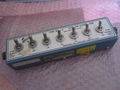
The external power supply and oscilloscope are connected by a removable cable with a Jones plug on one end and a Jones socket on the other end. Units with serial numbers from 101 through 1739 use 12-pin Jones 2412 connectors; after that it is a 16-pin Jones connector. (Was a 16-pin Jones connector used or did they go directory from the 12-pin Jones connector to the 16-pin Amphenol power connector used by the 555?)
The voltages on the 12-pin connector are:
- Pin 1: +750 V, regulated
- Pin 2: +475 V, regulated
- Pin 3: +350 V, unregulated
- Pin 4: +225 V, regulated
- Pin 5: +150 V, regulated
- Pin 6: Ground
- Pin 7: −250 V, regulated
- Pin 8: +180 V, unregulated
Later 517A units uses the same cable as the 551 and 555. Although they use the same cable, they are completely incompatible – the voltages are different. The 517's external power supply provides +750 V to the indicator unit. The highest voltage provided by the 555 and 551 power supplies is +500 V. Also, for example, the 517A has +180 V on pin 8 of the 16-pin connector while the 555 and 551 have -150 V on pin 8.
Distributed Amplifiers
The 517 makes extensive use of the distributed amplifier concept. Originally the 5XP CRT was used, which has 38 V/cm vertical deflection sensitivity when operated with 24 kV acceleration voltage. (Is this correct? It doesn't agree with the 5XP datasheet.)
Since the vertical sensitivity at the input connector is 0.1 V/cm, we can calculate that the voltage gain from the input connector to the vertical deflection plates is 380. For 4 cm deflection, a 152 V differential output swing is required. There are DC blocking capacitors at various places in the signal path. The slowest sweep is 20 μs/cm. The 517 is not designed for low-frequency use.
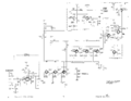
The vertical signal path is as follows:
- Optional B170-V external input attenuator
- Gain Stage 1: single-ended, six sections, distributed, 6AK5 pentodes
- Gain Stage 2: single-ended, six sections, distributed, 6AK5 pentodes
- Gain Stage 3: single-ended, seven sections, distributed, 6AK5 pentodes
- Trig Pickoff: one common-cathode 6CB6 pentode
- Signal Delay: 51 feet of RG63U 125-ohm coaxial cable (65ns)
- Phase Splitter: single-ended in, differential out, three sections, distributed, 6CB6 pentode
- Gain Stage 4: differential, six sections, distributed, 6CB6 pentodes
- Gain Stage 5: differential, twelve sections, distributed, 6CB6 pentodes
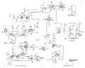
There is a trigger amplifier in the 517 which can take its input from an external source, or from the trigger pickoff in the vertical pre-amp, or from the internal rate generator circuit. The trigger amplifier circuit has five stages:
- Phase Splitter: 6J6 dual-triode connected as a differential amplifier
- Gain Stage 1: single-ended, three sections, distributed, 6AK5 pentodes
- Gain Stage 2: single-ended, three sections, distributed, 6AK5 pentodes
- Gain Stage 3: single-ended, common-cathode, 6AG7 pentode
- Gain Stage 4: single-ended, common-cathode, 6AG7 pentode
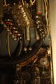
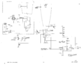
High Voltage Power Supply
The 517 uses 24 kV total acceleration voltage on the CRT. This is generated by the Type 420 High Voltage Power Supply subsystem in the 517. It uses a 1.8 kHz oscillator to produce the high voltage, unlike other Tek scopes which use HV oscillators in the ultrasonic range.
The 517 has a switch on the front panel that selects between normal vertical sensitivity, which uses the full 24 kV acceleration voltage, and "X2" mode, which drops the acceleration voltage to 12 kV for a doubling of the vertical sensitivity. The control works by switching the voltage division ratio of the feedback to the error amplifier in the HV supply.
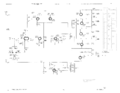
CRTs Used in the 517
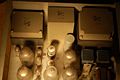
517 units with serial numbers 101 through 925 use the DuMont 5XP CRT. Later units use a Tek-made CRT, the T517PxH/T54PxH, where "x" designates the phosphor type: 1, 2, 7, 11, or 16. The 5XP used multi-band acceleration and has three anode connections, at 6.6 kV, 13.3 kV, and 20 kV. The Tek-made CRT has just one anode connection, 20 kV, and has 15 V/cm sensitivity at 24 kV total acceleration voltage.
The 517 might be the only Tektronix instrument to have a part made of wood - a support for a large electrolytic capacitor, C826, which filters probe power.
Comparison of 517 with 547
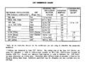
In 1965, following the introduction of the 50 MHz 547, the 517 was discontinued. The 547 uses a non-distributed solid-state vertical amplifier, tunnel diode triggering, and a 6.5 V/cm CRT, thereby achieving good performance with lower cost, size, weight, complexity, and power consumption than the 517.
| 517A | 547 with 1A1 | |
|---|---|---|
| Bandwidth | 50 MHz | 50 MHz |
| Sensitivity | 50 mV/cm | 50 mV/cm |
| Cost in 1964 | $3500 | $2475 |
| Size | scope + power supply | all in one |
| Weight | 148 lb / 67 kg | 71 lb / 32 kg |
| Complexity | 130 tubes | 45 tubes |
| Power Consumption | 1250 W | 510 W |
Some 517 modification kits are listed on page 181 of the 1959 catalog.
Tek sold the 108 pulse generator as a tool for maintaining the 517, since a fast scope requires a fast pulse generator to test it.
The P170CF cathode-follower probe was designed for use with the 517.
Links
- Final Report on Tektronix MILSPEC High Speed Scope (PDF, cleaned up and OCR)
- Final Report on Tektronix MILSPEC High Speed Scope (5MB, PDF, cleaned up)
- Final Report on Tektronix MILSPEC High Speed Scope (220MB, PDF, original)
- Flynn and Johnson "Fast Grey Wedge Analyzer for High Input Rates"
- Thomas and Hearst, "An Electronic Scheme for Measurement of Exploding Wire Energy"
Pictures of 517
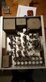
-
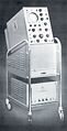
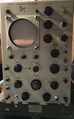
front
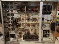
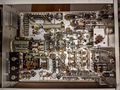
-
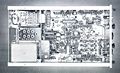
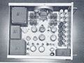
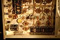
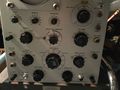
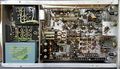
bottom internal
-
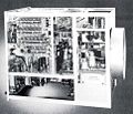
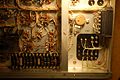
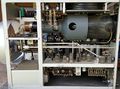
right internal
-
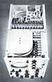
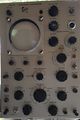
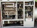
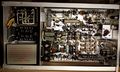
top internal
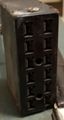
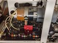
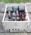
-
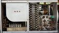
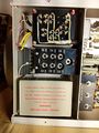
power supply internal
-
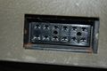
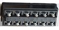
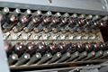
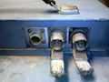
12-pin Jones socket on power supply
-
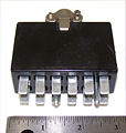
12-pin Jones plug
-
Original Tek 517 cable with Jones plug
-
12-pin Jones plug inside
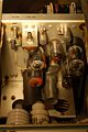
-
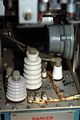
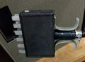
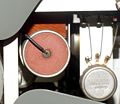
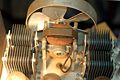
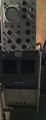
High voltage supply
-
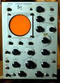
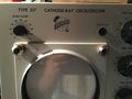
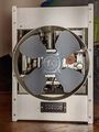
Front view
-
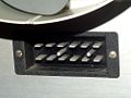
12-pin Jones connector on indicator unit
-
Left internal view
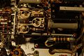
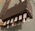
-
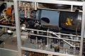
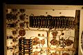
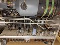
Distributed vertical output amplifier
-
Wooden support for capacitor C826
-
Tek CRT Reference Chart
-

-
-
-
-
-
-

-
-
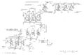
Vertical pre-amplifier circuit
-
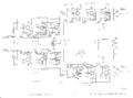
Vertical amplifier circuit
-
Trigger amplifier circuit
-
-
CRT circuit
-

-
High-voltage power supply circuit
-
-
-
-

-

-
-
-
-
-
-
Direct CRT access mod
-
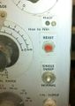
Single-sweep mod
-
-
-
-
-
-
-
-
-
-
-
-
-

-
-
-

517 with 5XP CRT
-
517 with 5XP CRT
-
-
-
-
-


Pictures of 517A
-
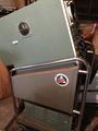
517A Front
-
517A Power Supply
-
517A with cart


