TG501: Difference between revisions
No edit summary |
No edit summary |
||
| (18 intermediate revisions by 5 users not shown) | |||
| Line 1: | Line 1: | ||
{{TM500 | mfg=Tektronix | type=TG501 | function=time mark generator | class=pulse generator | image=Tek tg501 on.JPG | introduced=1974 | discontinued=1995 | | {{TM500 | mfg=Tektronix | type=TG501 | function=time-mark generator | class=pulse generator | image=Tek tg501 on.JPG | introduced=1974 | discontinued=1995 | | ||
manuals= | manuals= | ||
* [ | '''TG501''' | ||
* [[Media:TG501 schematics.pdf| | * [[Media:070-1576-00.pdf|TG501 Manual 070-1576-00]] | ||
* [[Media:070-1576-02.pdf|TG501 Manual 070-1576-02]] (OCR, stitched schematics) | |||
* [[Media:050-1425-02.pdf|TG501 Product Mod 050-1425-02]] | |||
* [[Media:TG501 schematics.pdf|TG501 Schematics, stitched]] | |||
'''TG501A''' | |||
* [[Media:070-7373-00.pdf|TG501A Manual 070-7373-00]] | |||
}} | }} | ||
* Option 01 adds a 5MHz tempature-compensated crystal oscillator (Y50), and a TTL decade counter (U50) for a stable, precise internal clock. | |||
There is also a TG501A. | |||
Note the [ | Note the [https://www.eevblog.com/forum/repair/tektronix-tg501-out-put-problem/ output must be terminated into 50 Ω] or there may be no signal at all. | ||
{{BeginSpecs}} | |||
{{Spec | Interval | 1 ns to 5 s in 1−2−5 sequence }} | |||
{{Spec | Timing accuracy | Stability 1×10<sup>-5</sup>, long-term drift 1×10<sup>-5</sup> per month (with Option 1, 5×10<sup>-7</sup> / 1×10<sup>-7</sup> per month) }} | |||
{{Spec | Error Readout | Accuracy 1 digit (±0.1% points), Range to ±7.5% }} | |||
{{Spec | Amplitude | ≥1 V peak on 5 s through 10 ns; ≥750 mV<sub>p-p</sub> on 5 ns and 2 ns; ≥200 mV<sub>p-p</sub> on 1 ns (separate output) (all into 50 Ω) }} | |||
{{Spec | Trigger Output | Slaved to marker output from 5 s through 100 ns. Remains at 100 ns for all faster markers }} | |||
{{Spec | External Reference Input | 1 MHz, 5 MHz or 10 MHz; TTL compatible (internally hard wired so output frequencies counted down to 1 MHz) }} | |||
{{EndSpecs}} | |||
== | ==Rear Interface Signals== | ||
<small> | |||
{| class="wikitable" | |||
|- | |||
! colspan="2" | Connector Pin | |||
! | ! rowspan="2" | Description | ||
|- | |||
! Signal | |||
! Return | |||
|- | |||
| 28A || 27A || Marker Out (requires front BNC disconnection) | |||
|- | |||
| 27B || 28B || Trigger Out (requires front BNC disconnection) | |||
|- | |||
| 25A || 26A || Internal 1 MHz Clock Out (TTL) | |||
|- | |||
| 24B || 25B || External Clock Input | |||
|- | |- | ||
| | | 26B || 22B || Data Good (High when BCD data valid) | ||
|- | |- | ||
| | | 17A..20A || 22B || bit 4..1 BCD Display data, MSD | ||
|- | |- | ||
| | | 21A..24A || 22B || bit 4..1 BCD Display data, LSD | ||
|- | |||
| 16A || 22B || Fast=Low, Slow=High | |||
|} | |} | ||
</small> | |||
* | |||
* | ==Internals== | ||
* | The TG501 internally produces a 1 MHz reference clock, either from an internal crystal oscillator, or from an externally supplied frequency. | ||
* | |||
A 100 MHz VCO is phase-locked to this reference frequency (in fixed-frequency mode) or to the output of a variable 1 MHz astable multivibrator (in variable frequency mode). | |||
When the variable oscillator is in use, its frequency is digitally compared to the fixed 1 MHz reference and displayed as a deviation in percent with a pair of LEDs indicating the sign (fast or slow). | |||
A chain of dividers running off the 100 MHz clock provide the selectable output markers. | |||
The 1 ns output uses a [[step recovery diode]] (HP 5082-8872, part [[152-0503-00]]). | |||
==Links== | |||
* See the [[TG501/Repairs]] page for repair information. | |||
* [https://www.youtube.com/watch?v=U5LQpqwqNIU Tek TG501A Time Mark Gen Restoration] by NFM @ YouTube | |||
* [https://www.youtube.com/watch?v=FIe9WzdIZ9g TG501 Repair and Calibration] by Zenwizard Studios @ YouTube | |||
* [https://www.youtube.com/watch?v=rF5V7D0VZeE TG501 In-Depth Troubleshooting of a Stubborn Unit] by Zenwizard Studios @ YouTube | |||
* [https://www.youtube.com/watch?v=1t7ndiKzYI8 TG501 In-Depth Troubleshooting of a Stubborn Unit Part 2] by Zenwizard Studios @ YouTube | |||
* [https://www.youtube.com/watch?v=yl29OOxyNf0 Tektronix TG501A Refresh and Check For a Viewer] by Zenwizard Studios @ YouTube | |||
{{Documents|Link=TG501}} | |||
== | ==Prices== | ||
{| class="wikitable sortable" | |||
|- | |||
! Year | |||
! 1975 | |||
|- | |||
! Catalog Price | |||
| align="right" | $745 | |||
|- | |||
! In 2023 Dollars | |||
| align="right" | $4,300 | |||
|} | |||
==Pictures== | ==Pictures== | ||
===TG501=== | |||
<gallery> | |||
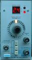
Tek tg501 on.JPG | TG501 early version | |||
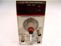
Tg 501 late.jpg | TG501 late version | |||
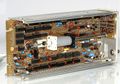
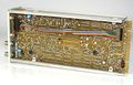
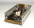
Tek tg501 internal1.jpg | |||
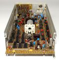
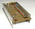
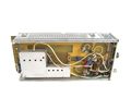
Tek tg501 internal2.jpg | |||
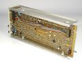
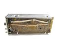
Tek tg501 internal3.jpg | |||
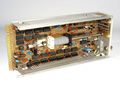
Tek tg501 internal4.jpg | |||
Tek tg501 internal5.jpg | |||
Tek tg501 internal6.jpg | |||
Tek tg501 internal7.jpg | |||
Tek tg501 early left.jpg | TG501 early version | |||
Tek tg501 early right.jpg | TG501 early version | |||
Tek tg501 waveform.jpg | TG501 output waveform | |||
</gallery> | |||
===TG501A=== | |||
<gallery> | <gallery> | ||
Tek tg501a.jpg | |||
Tek tg501a.jpg | |||
</gallery> | </gallery> | ||
==Parts== | |||
{{Parts|TG501}} | |||
{{Parts|TG501A}} | |||
[[Category:Time mark generators]] | |||
Latest revision as of 11:55, 4 March 2024

The Tektronix TG501 is a time-mark generator plug-in for the TM500 system.
- Option 01 adds a 5MHz tempature-compensated crystal oscillator (Y50), and a TTL decade counter (U50) for a stable, precise internal clock.
There is also a TG501A.
Note the output must be terminated into 50 Ω or there may be no signal at all.
Key Specifications
| Interval | 1 ns to 5 s in 1−2−5 sequence |
|---|---|
| Timing accuracy | Stability 1×10⁻⁵, long-term drift 1×10⁻⁵ per month (with Option 1, 5×10⁻⁷ / 1×10⁻⁷ per month) |
| Error Readout | Accuracy 1 digit (±0.1% points), Range to ±7.5% |
| Amplitude | ≥1 V peak on 5 s through 10 ns; ≥750 mVp-p on 5 ns and 2 ns; ≥200 mVp-p on 1 ns (separate output) (all into 50 Ω) |
| Trigger Output | Slaved to marker output from 5 s through 100 ns. Remains at 100 ns for all faster markers |
| External Reference Input | 1 MHz, 5 MHz or 10 MHz; TTL compatible (internally hard wired so output frequencies counted down to 1 MHz) |
Rear Interface Signals
| Connector Pin | Description | |
|---|---|---|
| Signal | Return | |
| 28A | 27A | Marker Out (requires front BNC disconnection) |
| 27B | 28B | Trigger Out (requires front BNC disconnection) |
| 25A | 26A | Internal 1 MHz Clock Out (TTL) |
| 24B | 25B | External Clock Input |
| 26B | 22B | Data Good (High when BCD data valid) |
| 17A..20A | 22B | bit 4..1 BCD Display data, MSD |
| 21A..24A | 22B | bit 4..1 BCD Display data, LSD |
| 16A | 22B | Fast=Low, Slow=High |
Internals
The TG501 internally produces a 1 MHz reference clock, either from an internal crystal oscillator, or from an externally supplied frequency.
A 100 MHz VCO is phase-locked to this reference frequency (in fixed-frequency mode) or to the output of a variable 1 MHz astable multivibrator (in variable frequency mode). When the variable oscillator is in use, its frequency is digitally compared to the fixed 1 MHz reference and displayed as a deviation in percent with a pair of LEDs indicating the sign (fast or slow).
A chain of dividers running off the 100 MHz clock provide the selectable output markers.
The 1 ns output uses a step recovery diode (HP 5082-8872, part 152-0503-00).
Links
- See the TG501/Repairs page for repair information.
- Tek TG501A Time Mark Gen Restoration by NFM @ YouTube
- TG501 Repair and Calibration by Zenwizard Studios @ YouTube
- TG501 In-Depth Troubleshooting of a Stubborn Unit by Zenwizard Studios @ YouTube
- TG501 In-Depth Troubleshooting of a Stubborn Unit Part 2 by Zenwizard Studios @ YouTube
- Tektronix TG501A Refresh and Check For a Viewer by Zenwizard Studios @ YouTube
Documents Referencing TG501
| Document | Class | Title | Authors | Year | Links |
|---|---|---|---|---|---|
| 070-2088-00.pdf | Book | TM500 Series Rear Interface Data Book | 1975 | AF501 • AM501 • AM502 • DC501 • DC502 • DC503 • DC504 • DC505 • DC505A • DM501 • DM502 • FG501 • FG502 • FG503 • MR501 • PG501 • PG502 • PG505 • PG506 • PG508 • PS501 • PS502 • PS503 • PS503A • PS505 • RG501 • SC501 • SC502 • SG502 • SG503 • TG501 | |
| 070-2088-01.pdf | Book | TM500 Series Rear Interface Data Book | 1976 | AF501 • AM501 • AM502 • AM511 • DC501 • DC502 • DC503 • DC504 • DC505 • DC505A • DD501 • DM501 • DM502 • FG501 • FG502 • FG503 • FG504 • LA501 • MR501 • PG501 • PG502 • PG505 • PG506 • PG508 • PS501 • PS502 • PS503 • PS503A • PS505 • RG501 • SC501 • SC502 • SG502 • SG503 • SG504 • SW503 • TG501 • TR501 • TR502 | |
| Tekscope 1976 V8 N1.pdf | Article | Troubleshooting Phase Lock Loops | John Mulvey | 1976 | TG501 |
Prices
| Year | 1975 |
|---|---|
| Catalog Price | $745 |
| In 2023 Dollars | $4,300 |
Pictures
TG501
-
TG501 early version
-
TG501 late version
-
-
-
-
-
-
-
-
TG501 early version
-
TG501 early version
-
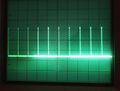
TG501 output waveform


TG501A

Parts
Some Parts Used in the TG501
| Part | Part Number(s) | Class | Description | Used in |
|---|---|---|---|---|
| 152-0503-00 | 152-0503-00 | Discrete component | 500 ps step recovery diode | 1503C • TG501 • TG501A |
| Signetics N8T06B | 156-0379-00 | Monolithic integrated circuit | 7-segment driver | TG501 |
Some Parts Used in the TG501A
| Part | Part Number(s) | Class | Description | Used in |
|---|---|---|---|---|
| 152-0503-00 | 152-0503-00 | Discrete component | 500 ps step recovery diode | 1503C • TG501 • TG501A |