514: Difference between revisions
No edit summary |
m (add 5 Hz lower bandwidth limit in 511 description) |
||
| (15 intermediate revisions by 2 users not shown) | |||
| Line 1: | Line 1: | ||
{{Oscilloscope Sidebar | | {{Oscilloscope Sidebar | ||
|manufacturer=Tektronix | |||
summary=10 MHz | |series= | ||
image=Tek 514d front.jpg | | |model=514 | ||
caption=Tektronix 514 front | | |summary=10 MHz scope | ||
introduced=1949 | | |image=Tek 514d front.jpg | ||
discontinued=1956 | |caption=Tektronix 514 front | ||
|introduced=1949 | |||
manuals= | |discontinued=1956 | ||
* [ | |designers=Dick Rhiger | ||
|manuals= | |||
* [[Media:IM-514D.pdf|Tektronix 514D Manual]] | |||
* [[Media:Tek 514 history parts list.pdf|Tektronix 514 History Parts List]] | |||
}} | }} | ||
The '''Tektronix 514''' is a monolithic general-purpose oscilloscope introduced in 1949 or 1950. | The '''Tektronix 514''' is a monolithic general-purpose oscilloscope introduced in 1949 or 1950. | ||
| Line 14: | Line 17: | ||
It was designed by Tektronix engineers [[Bob Davis]] and [[Dick Rhiger]]. | It was designed by Tektronix engineers [[Bob Davis]] and [[Dick Rhiger]]. | ||
Using a three-section | Using a three-section [[distributed amplifier]], it provides frequency response from DC to 10 MHz. | ||
Prior to the 514, customers had to choose between an instrument with 10 MHz bandwidth (the [[511]]) ''or'' an instrument with | Prior to the 514, customers had to choose between an instrument with 5 Hz to 10 MHz bandwidth (the [[511]]) | ||
''or'' an instrument with DC–2 MHz response (the [[512]]). The 514 provides DC response ''and'' 10 MHz bandwidth. | |||
The 514 provides DC response ''and'' 10 MHz bandwidth. | |||
Throughout its production run, a 'D' variant was available (514D, with the 'D' being stamped in by hand | |||
on some models), which has a 24-section 250 ns lumped L-C [[delay line]]. | |||
Throughout its production run, a 'D' variant was available (514D, with the 'D' being stamped in by hand on some models) which has a 24-section 250 ns lumped L-C [[delay line]]. | |||
There was also an 'A' version (514-A & 514-AD respectively), which appears to have been available in 1954. | There was also an 'A' version (514-A & 514-AD respectively), which appears to have been available in 1954. | ||
''(There were also some models marked 'Series A', which may have been a predecessor to the 514A? | ''(There were also some models marked 'Series A', which may have been a predecessor to the 514A? How does the 514AD differ from the 514D?)'' | ||
It has no [[thermal cutoff]]. | It has no [[thermal cutoff]]. | ||
| Line 36: | Line 30: | ||
{{BeginSpecs}} | {{BeginSpecs}} | ||
{{Spec | Frequency response | DC to 10 MHz }} | {{Spec | Frequency response | DC to 10 MHz }} | ||
{{Spec | Input impedance |1 MΩ // 30 pF }} | {{Spec | Input impedance | 1 MΩ // 30 pF }} | ||
{{Spec | Vertical deflection | 100 V/cm down to 300 mV/cm (DC) / 30 mV/cm (AC), | {{Spec | Vertical deflection | 100 V/cm down to 300 mV/cm (DC) / 30 mV/cm (AC), 1–3–10 sequence}} | ||
{{Spec | Weight | | {{Spec | Weight | 28.1 kg (62 pounds) }} | ||
{{Spec | Power consumption | 375 W }} | {{Spec | Power consumption | 375 W }} | ||
{{EndSpecs}} | {{EndSpecs}} | ||
==Internals== | |||
The 514 uses a [[5CPA]] CRT with a total accelerating voltage of 3 kV (−1.5 kV on the CRT cathode and +1.5 kV on the CRT anode). | |||
The standard [[phosphor]] for a 514 was P1. | |||
The deflection sensitivity of the CRT is approximately 27 V/cm vertical and 32 V/cm horizontal. | |||
The power supply is regulated based on a −140 V reference produced by an [[OD3]] gas regulator tube. | |||
The +225 V supply uses three [[5V4G]] rectifier tubes in parallel. | |||
==Links== | ==Links== | ||
* [ | * [https://paulcarbone.com/blog/?p=909 Paul's research on models, variants, and years available] | ||
* [[Media:Tektronix Photo Manual 1952.pdf| Tektronix Photo Manual 1952]] | |||
==Pictures== | ==Pictures== | ||
'''514''' | |||
<gallery> | |||
Tek 514d front.jpg | Front | |||
Tek 514 with bk curve tracer.jpg | 514AD with B&K Curve Tracer | |||
Tek 514d dist amp.jpg | Distributed vertical amp | |||
Tek 514d delay trimmers.jpg | Delay line trimmer caps | |||
Tek 514d bottom.jpg | Bottom view | |||
Tek514-PowerSupply.jpg | Power Supply | |||
Tek514-upperDeckRear.jpg | Upper Deck, rear | |||
Tek514-upperDeckFront.jpg | Upper Deck, front | |||
Tek514-lowerDeckFront.jpg | Lower Deck, front | |||
Tek514-lowerDeckRear.jpg | Lower Deck, rear | |||
Tek514-fanMotor.jpg | Fan Motor | |||
Tek514-lineSocket.jpg | Line Socket | |||
Tek 514d-vert schem2.png | Vertical amp schematic | |||
Tek_514_Vertical_preamp_early.jpg | Vertical preamp, early | |||
Tek_514_HV_PS_early.jpg | HV Power Supply, early | |||
</gallery> | |||
'''514AD''' | |||
<gallery> | <gallery> | ||
Tek 514ad 5535 1.jpg | |||
Tek 514ad 5535 2.jpg | |||
Tek 514ad 5535 3.jpg | |||
Tek 514ad 5535 4.jpg | |||
Tek 514ad 5535 5.jpg | |||
Tek 514ad 5535 6.jpg | |||
Tek 514ad 5535 7.jpg | |||
Tek 514ad 5535 8.jpg | |||
Tek 514ad 5535 9.jpg | |||
Tek 514ad 5535 10.jpg | |||
</gallery> | </gallery> | ||
==Components== | |||
{{Parts|514}} | |||
{{Parts|514D}} | |||
{{Parts|514A}} | |||
{{Parts|514AD}} | |||
[[Category:Monolithic tube scopes]] | [[Category:Monolithic tube scopes]] | ||
Latest revision as of 19:13, 16 March 2024
The Tektronix 514 is a monolithic general-purpose oscilloscope introduced in 1949 or 1950.
It was designed by Tektronix engineers Bob Davis and Dick Rhiger.
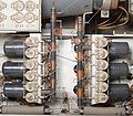
Using a three-section distributed amplifier, it provides frequency response from DC to 10 MHz. Prior to the 514, customers had to choose between an instrument with 5 Hz to 10 MHz bandwidth (the 511) or an instrument with DC–2 MHz response (the 512). The 514 provides DC response and 10 MHz bandwidth.
Throughout its production run, a 'D' variant was available (514D, with the 'D' being stamped in by hand on some models), which has a 24-section 250 ns lumped L-C delay line. There was also an 'A' version (514-A & 514-AD respectively), which appears to have been available in 1954. (There were also some models marked 'Series A', which may have been a predecessor to the 514A? How does the 514AD differ from the 514D?)
It has no thermal cutoff.
Key Specifications
| Frequency response | DC to 10 MHz |
|---|---|
| Input impedance | 1 MΩ // 30 pF |
| Vertical deflection | 100 V/cm down to 300 mV/cm (DC) / 30 mV/cm (AC), 1–3–10 sequence |
| Weight | 28.1 kg (62 pounds) |
| Power consumption | 375 W |
Internals
The 514 uses a 5CPA CRT with a total accelerating voltage of 3 kV (−1.5 kV on the CRT cathode and +1.5 kV on the CRT anode). The standard phosphor for a 514 was P1. The deflection sensitivity of the CRT is approximately 27 V/cm vertical and 32 V/cm horizontal.
The power supply is regulated based on a −140 V reference produced by an OD3 gas regulator tube. The +225 V supply uses three 5V4G rectifier tubes in parallel.
Links
Pictures
514
-
Front
-
514AD with B&K Curve Tracer
-
Distributed vertical amp
-
Delay line trimmer caps
-
Bottom view
-
Power Supply
-
Upper Deck, rear
-
Upper Deck, front
-
Lower Deck, front
-
Lower Deck, rear
-
Fan Motor
-
Line Socket
-
Vertical amp schematic
-
Vertical preamp, early
-
HV Power Supply, early
514AD
Components
Some Parts Used in the 514
| Part | Part Number(s) | Class | Description | Used in |
|---|---|---|---|---|
| 0D3 | 154-003 • 154-0003-00 | Gas Discharge Tube (Voltage regulator) | 153 V voltage reference | 511 • 511A • 513 • 514 |
| 12AT7 | 154-0039-00 | Vacuum Tube (Dual Triode) | dual high-gain triode | 161 • 180 • 310 • 310A • 315 • 316 • 360 • 502 • 502A • 511A • 512 • 513 • 513D • 514 • 514AD • 514D • 516 • 524 • 529 • RM529 • 544 • 546 • 547 • 556 • 565 • 570 • 3A2 • 75 • 3A75 • 1M1 • A • B • C • G • H • K • L • ML • M • N • K • R • S • Z • Keithley 610B |
| 5CPA | 154-0063-00 | CRT | 5" CRT with electrostatic deflection | 512 • 514 |
| 5V4G | 154-008 • 154-0008-00 | Vacuum Tube (Dual Rectifier) | dual rectifier | 104 • 104A • 160 • 511A • 514 |
| 6AG7 | 154-012 • 154-0012-00 | Vacuum Tube (Pentode) | 9 Watt power pentode | 104 • 104A • 105 • 112 • 511 • 511A • 512 • 513 • 514 • 517 • 517A • 524 |
| 6DK6 | 154-0149-00 • 154-0367-00 | Vacuum Tube (Pentode) | high-frequency miniature pentode | 180 • 503 • 513 • 514 • 541 • 543 • 535 • 545 • 545A • 551 • 555 |
Some Parts Used in the 514D
| Part | Part Number(s) | Class | Description | Used in |
|---|---|---|---|---|
| 12AT7 | 154-0039-00 | Vacuum Tube (Dual Triode) | dual high-gain triode | 161 • 180 • 310 • 310A • 315 • 316 • 360 • 502 • 502A • 511A • 512 • 513 • 513D • 514 • 514AD • 514D • 516 • 524 • 529 • RM529 • 544 • 546 • 547 • 556 • 565 • 570 • 3A2 • 75 • 3A75 • 1M1 • A • B • C • G • H • K • L • ML • M • N • K • R • S • Z • Keithley 610B |
Some Parts Used in the 514A
- (no results)
Some Parts Used in the 514AD
| Part | Part Number(s) | Class | Description | Used in |
|---|---|---|---|---|
| 12AT7 | 154-0039-00 | Vacuum Tube (Dual Triode) | dual high-gain triode | 161 • 180 • 310 • 310A • 315 • 316 • 360 • 502 • 502A • 511A • 512 • 513 • 513D • 514 • 514AD • 514D • 516 • 524 • 529 • RM529 • 544 • 546 • 547 • 556 • 565 • 570 • 3A2 • 75 • 3A75 • 1M1 • A • B • C • G • H • K • L • ML • M • N • K • R • S • Z • Keithley 610B |


