User:Peter: Difference between revisions
No edit summary |
No edit summary |
||
| Line 63: | Line 63: | ||
File:P6202-risetime-7s12-100ps.jpg | P6202 rise time | File:P6202-risetime-7s12-100ps.jpg | P6202 rise time | ||
File:P6202-risetime-7s12-1ns.jpg | P6202 rise time | File:P6202-risetime-7s12-1ns.jpg | P6202 rise time | ||
File:P6230-rt1.jpg | P6230 Rise time measured on a [[7S12]] with [[S-52]] and [[S-4]] heads, P6230 ground sleeve connected directly at S-52 output (no ground lead) | |||
File:P6230-rt2.jpg | P6230 Rise time without ground lead: 9.2 * 20 ps = 184 ps (equiv. to 1.9 GHz bandwidth) | |||
File:P6230-rt3.jpg | P6230 Rise time - Effect of using the "low inductance" ground lead - rise time 400 ps, bandwidth 875 MHz | |||
File:P6230-rt4.jpg | P6230 Rise time - Using the 250 mm alligator ground lead - severe pulse distortion, rise time ~3 ns (115 MHz)! | |||
File:Tek7904-7a19-7b92a-1010mhz-hfsync.jpg | A 7B92A (B098xxx) displaying a 1.01 GHz sine in HF Sync mode (7904 mainframe, 7A19 amplifier) | File:Tek7904-7a19-7b92a-1010mhz-hfsync.jpg | A 7B92A (B098xxx) displaying a 1.01 GHz sine in HF Sync mode (7904 mainframe, 7A19 amplifier) | ||
| Line 79: | Line 84: | ||
File:7b85-risetime-5n.jpg | 7B85 used for rise time measurement | File:7b85-risetime-5n.jpg | 7B85 used for rise time measurement | ||
File:7b85-pulse-width.jpg | 7B85 used for pulse width measurement | File:7b85-pulse-width.jpg | 7B85 used for pulse width measurement | ||
File:7b85-period-2.jpg | 7B85 used for pulse period measurement | File:7b85-period-2.jpg | 7B85 used for pulse period measurement | ||
File:7b85-period-1.jpg | 7B85 used for pulse period measurement | File:7b85-period-1.jpg | 7B85 used for pulse period measurement | ||
| Line 93: | Line 99: | ||
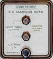
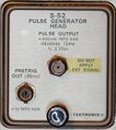
File:7s12-s52-incident.jpg | 7S12 displaying the incident pulse from an S-52 (nom. < 25 ps) through an S-6 head (nom. < 30 ps) | File:7s12-s52-incident.jpg | 7S12 displaying the incident pulse from an S-52 (nom. < 25 ps) through an S-6 head (nom. < 30 ps) | ||
File:7s12-self-portrait.jpg | 7S12/S-6/S-52 "Self Portrait" - pulse reflected on S-6 "through" path (approx. 120 ps one way) | File:7s12-self-portrait.jpg | 7S12/S-6/S-52 "Self Portrait" - pulse reflected on S-6 "through" path (approx. 120 ps one way) | ||
File:7s12-s52-pulse-1.jpg | Full pulse pattern of a 7S12/S-52 in real time (top trace) and sampled (bottom trace) shown simultaneously on [[7844]]. 7S12 trace at slowest possible sweep. | |||
File:7s12-s52-pulse-2.jpg | S-52 pulse in real time (top trace) and sampled (bottom trace) shown simultaneously on [[7844]]. Approximately equal time scales. | |||
File:Tri-1k w.jpg | sub-millivolt triangle signal displayed through 7A22, BW=1 kHz | File:Tri-1k w.jpg | sub-millivolt triangle signal displayed through 7A22, BW=1 kHz | ||
Revision as of 08:11, 17 January 2016
Scopes
Plugins
Screen shots
-
Faster-than-light beam on 7104? Using a 067-0587-02 calibration fixture at maximum amplitude produces this trace spanning 1.2 Div horizontally at 200 ps/Div and 8 Div vertically. Trace length is (1.2² + 8²)½ × 8.5 mm = 68.8 mm, travelled in 1.2 × 200 ps = 240 ps. Apparent speed is therefore 68.8×10⁻³ / 240×10-12 m/s or 2.86×10⁸ m/s. Very near miss ...
-
Rise time measurement. 150 ps risetime pulse from 067-0587-02 at 100 Hz repetition rate. Measured 240 ps (corrected for 150 ps fixture rise time: 190 ns = 1.8 GHz)
-
Rise time measurement as before, 1000 Hz repetition rate at same brightness settings.
-
7104 recording a single shot pulse (from 067-0587-02) at 200ps/Div. Camera: Nikon D7100, 50 mm f/1.4, ISO 3200, 1/2 s. CRT filter not removed.
-
7104 recording 1 GHz sine, single shot at 200ps/Div. Camera: Nikon D7100, 50 mm f/1.4, ISO 3200, 1/2 s. CRT filter not removed. CRT amplification loss is evident around the center line.
-
BC337 on 7CT1N
-
P6202 rise time
-
P6202 rise time
-
P6230 Rise time without ground lead: 9.2 * 20 ps = 184 ps (equiv. to 1.9 GHz bandwidth)
-
P6230 Rise time - Effect of using the "low inductance" ground lead - rise time 400 ps, bandwidth 875 MHz
-
P6230 Rise time - Using the 250 mm alligator ground lead - severe pulse distortion, rise time ~3 ns (115 MHz)!
-
A 7B92A (B098xxx) displaying a 1.01 GHz sine in HF Sync mode (7904 mainframe, 7A19 amplifier)
-
A 7B92A (B098xxx) triggering a 974 MHz sine applied via 067-0587-02 calibration fixture
-
Signal beam interruption by readout seen on beam 2 of a 7844
-
Classic readout board diagnostic display
-
15 μV p-p triangle wave measured through 7A22. Using variable-persistence storage mode on a 7613 for noise filtering.
-
Tektronix 067-0587-02, gain mode, in horizontal slot
-
Tektronix 067-0587-02, gain mode, in vertical slot
-
7D14 screen picture - 500 MHz signal (7A19, 7B92A, 7904)
-
7B85 used for rise time measurement
-
7B85 used for rise time measurement
-
7B85 used for pulse width measurement
-
7B85 used for pulse period measurement
-
7B85 used for pulse period measurement
-
7S11/7T11, 1 GHz sine, smooth mode, on variable-persistence storage scope (7613)
-
7S11/7T11, 1 GHz sine, smooth mode
-
7S11/7T11, 1 GHz sine, normal mode
-
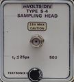
7S11/S-4 and 7T11A displaying 1 GHz sine
-
7S12 as a sampler displaying a 1 GHz signal (hi-res mode / storage)
-
7S12 as a sampler displaying a 1 GHz signal (hi-res mode / storage)
-
7S12 as a sampler displaying a 1 GHz signal (normal mode / non-storage)
-
7S12 displaying the incident pulse from an S-52 (nom. < 25 ps) through an S-6 head (nom. < 30 ps)
-
7S12/S-6/S-52 "Self Portrait" - pulse reflected on S-6 "through" path (approx. 120 ps one way)
-
Full pulse pattern of a 7S12/S-52 in real time (top trace) and sampled (bottom trace) shown simultaneously on 7844. 7S12 trace at slowest possible sweep.
-
S-52 pulse in real time (top trace) and sampled (bottom trace) shown simultaneously on 7844. Approximately equal time scales.
-
sub-millivolt triangle signal displayed through 7A22, BW=1 kHz
-
sub-millivolt triangle signal displayed through 7A22, BW=10 kHz
-
sub-millivolt triangle signal displayed through 7A22, BW=100 kHz
-
sub-millivolt triangle signal through 7A22, BW=1 MHz


