7B92: Difference between revisions
No edit summary |
No edit summary |
||
| Line 15: | Line 15: | ||
'''7B92A''' | '''7B92A''' | ||
* [[Media:070-1752-01.pdf|Tektronix 7B92A Operators Manual]] (OCR) | * [[Media:070-1752-01.pdf|Tektronix 7B92A Operators Manual]] (OCR) | ||
* [[Media:070-1751-02.pdf|Tektronix 7B92A Instruction Manual]]<small> / [https://bama.edebris.com/download/tek/7b92a-2/tek-7b92a.pdf alternate copy @ BAMA]</small> | * [[Media:070-1751-02.pdf|Tektronix 7B92A Instruction Manual]] (1987 rev., both circuit versions)<small> / [https://bama.edebris.com/download/tek/7b92a-2/tek-7b92a.pdf alternate copy @ BAMA]</small> | ||
}} | }} | ||
The '''Tektronix 7B92''' is a 500 MHz dual timebase plug-in for [[7000-series scopes]]. | The '''Tektronix 7B92''' is a 500 MHz dual timebase plug-in for [[7000-series scopes]]. | ||
| Line 53: | Line 53: | ||
7b92a-front.jpg | 7B92A front | 7b92a-front.jpg | 7B92A front | ||
Tek 7b92a front2.jpg | 7B92A | Tek 7b92a front2.jpg | 7B92A | ||
Tek 7b92a right.jpg | 7B92A right | Tek 7b92a right.jpg | 7B92A right (late S/N, [[Hypcon]]-packaged [[155-0150-00]] trigger detector circuits) | ||
Tek 7b92a left.jpg | 7B92A left | Tek 7b92a left.jpg | 7B92A left (late S/N) | ||
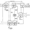
Tek 7b92a block.png | 7B92A block diagram | Tek 7b92a block.png | 7B92A block diagram | ||
7b92a-triggering-974mhz.jpg | A 7B92A (B098xxx) triggering a 974 MHz sine applied to a [[7904]] mainframe via a 067-0587-02 calibration fixture (maximum triggerable frequency for this specimen). | 7b92a-triggering-974mhz.jpg | A 7B92A (B098xxx) triggering a 974 MHz sine applied to a [[7904]] mainframe via a 067-0587-02 calibration fixture (maximum triggerable frequency for this specimen). | ||
Revision as of 05:12, 9 December 2021
The Tektronix 7B92 is a 500 MHz dual timebase plug-in for 7000-series scopes. It was introduced along with the 7904 mainframe in 1972. In 1976, it was updated as the 7B92A.
An "HF Sync" triggering mode is provided in which the trigger level control varies the frequency of a built-in oscillator to lock on to the input for input signals from 100 to 500 MHz, providing higher sensitivity than the direct trigger (which is specified up to 500 MHz as well).
Internal jumpers are provided to configure the 7B92 for operation in 7800/7900 vs. slower mainframes, and to select whether the variable control affects the delaying or the delayed time base.
As a dual time base, the 7B92 uses the top field in the display readout for the sweep speed of the main and the bottom field for the delayed time base. The delay time can only be read from the 10-turn analog dial.
The 7B92 has no magnifier function but its regular sweep dial setting reaches down to 500 ps/Div. It has no provision for X-Y operation.
Key Specifications
| Sweep speed | 0.5 ns/Div to 0.2 s/Div, 1—2—5 sequence (variable up to 0.5 s/Div) |
|---|---|
| Delay time | 0 to 9.9 Div |
| Triggering | 0.5 Div or 100 mV up to 20 MHz, 1 Div or 500 mV up to 600 MHz |
| Jitter | < 50 ps at 600 MHz |
| Ext Trig input | 1 MΩ // 20 pF or 50 Ω |
Internals
The 7B92 uses a discrete trigger circuit containing 152-0177-02 tunnel diodes. Up to serial number B069999, the 7B92A used a trigger circuit with 155-0061-00 amplifiers and 152-0177-02 tunnel diodes. After that, the 7B92A used a 155-0061-00 trigger amplifier followed by a 155-0150-00 trigger detector.
The 7B92A uses one other custom IC, the 155-0049-xx sweep control circuit. The internal jumper for mainframe selection (7800/7900/7100 vs. slower) actually increases the minimum holdoff time on the slower mainframe selection by adding a 214 pF capacitor (C307 for 7B92, C835 for 7B92A) to pin 8 of the sweep control IC 155-0049-xx in parallel to the existing capacitors. This increases the minimum pulse width of the holdoff signal on pin B4 so that the sweep logic of slower mainframes can handle it properly. The effect of this jumper is only noticeable for sweep speeds of 20 μs/Div. and faster, since there the smallest shunt capacitance is used on pin 8, and the holdoff time is minimal.
Links
Pictures
-
7B92 front
-
7B92 right
-
7B92 left
-
7B92A front
-
7B92A
-
7B92A right (late S/N, Hypcon-packaged 155-0150-00 trigger detector circuits)
-
7B92A left (late S/N)
-
7B92A block diagram
-
A 7B92A (B098xxx) triggering a 974 MHz sine applied to a 7904 mainframe via a 067-0587-02 calibration fixture (maximum triggerable frequency for this specimen).
Custom ICs used in the 7B92A
| Page | Model | Part nos | Description | Designers | Used in |
|---|---|---|---|---|---|
| 155-0049-00 | M079G | 155-0049-00 • 155-0049-01 • 155-0049-02 | sweep control with lockout | Bill DeVey | 335 • 464 • 465 • 466 • 475 • 475A • 475M • 485 • 5B31 • 5B40 • 5B52 • 5B42 • 5B44 • 7B53A • 7B80 • 7B85 • 7B87 • 7B92A • 7B90P • 7B10 • 7B15 • SC502 • 7B42N • AN/USM-281C • 067-0657-00 |
| 155-0061-00 | M083 | 155-0061-00 • 155-0061-01 • 155-0061-02 | trigger amplifier | Hans Springer | 7B92 • 7B92A |
| 155-0150-00 | H473 | 155-0150-00 | trigger detector | Walt Ainsworth • Art Metz | 7904A • 7104 • 7B10 • 7B15 • 7B92A • SCD1000 |


