11A34: Difference between revisions
No edit summary |
No edit summary |
||
| Line 24: | Line 24: | ||
The 11A34 uses the same firmware as the [[11A32]]. | The 11A34 uses the same firmware as the [[11A32]]. | ||
Each of the four channels has its own M377 amplifier. | |||
The display outputs of the four amplifiers are combined in parallel and drive the 50 Ω impedance of the mainframe. | |||
The same is true of the trigger outputs of the four amplifiers. | |||
The version of the M377 used in the 11A34 has 200 Ω output impedance so that four of them in parallel create an equivalent source impedance of 50 Ω. | |||
The amplifiers can be connected in parallel because regardless of whether the amplifier's output is enabled: | |||
* each amplifier's output has a source impedance of 200 Ω so the two amplifiers in parallel match the 50 Ω spec of the [[11000 Series plug-in interface]]. | |||
* each amplifier's nominal common-mode output voltage is zero | |||
* each amplifier's nominal differential output voltage is zero | |||
See the block diagram below. | |||
{{BeginSpecs}} | {{BeginSpecs}} | ||
| Line 44: | Line 54: | ||
Each channel's attenuator module contains an [[M474]] buffer amplifier. | Each channel's attenuator module contains an [[M474]] buffer amplifier. | ||
Each of the attenuator modules drives an [[M377]] amplifier IC. | Each of the attenuator modules drives an [[M377]] amplifier IC. | ||
The 11A32 and 11A34 were originally intended to use Intel 8052 microcontrollers. | |||
However, during development, the firmware swelled beyond that chip's 8192-byte maximum on-chip ROM size. | |||
[[Doug Haines]] found an alternate supplier of 8051-compatible chips (OKI Semiconductor) that offered a 16Kbyte on-chip ROM, | |||
and that's what the plug-ins wound up with. The finished code size wound up at about 14 KB. | |||
The 11A34 contains two [[ACVS]] sample and hold modules. | The 11A34 contains two [[ACVS]] sample and hold modules. | ||
Revision as of 10:05, 25 December 2022

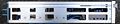
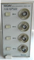
The Tektronix 11A34 is a four-channel vertical amplifier plug-in for 11000-series and DSA600-series scopes.
Option 23 added four P6134 probes.
There is also a later version, the 11A34V introduced in 1991, for video applications. Development of the 11A34V was managed by Murlan Kaufman. (See also 11T5H.) more Information needed
The 11A34 uses the same firmware as the 11A32.
Each of the four channels has its own M377 amplifier. The display outputs of the four amplifiers are combined in parallel and drive the 50 Ω impedance of the mainframe. The same is true of the trigger outputs of the four amplifiers. The version of the M377 used in the 11A34 has 200 Ω output impedance so that four of them in parallel create an equivalent source impedance of 50 Ω. The amplifiers can be connected in parallel because regardless of whether the amplifier's output is enabled:
- each amplifier's output has a source impedance of 200 Ω so the two amplifiers in parallel match the 50 Ω spec of the 11000 Series plug-in interface.
- each amplifier's nominal common-mode output voltage is zero
- each amplifier's nominal differential output voltage is zero
See the block diagram below.
Key Specifications
| Bandwidth | DC to 300 MHz, 100 MHz and 20 MHz BWL filters |
|---|---|
| Rise time | 1.2 ns in 1 GHz mainframe such as the 11402, 11402A. 11403, 11403A, DSA601A, or DSA602A |
| Deflection | 1 mV to 10 V/div in 1% calibrated steps |
| Input impedance | 50 Ω or 1 MΩ |
| Features |
|
Links
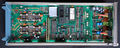
Internals
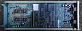
Each channel's attenuator module contains an M474 buffer amplifier. Each of the attenuator modules drives an M377 amplifier IC.
The 11A32 and 11A34 were originally intended to use Intel 8052 microcontrollers. However, during development, the firmware swelled beyond that chip's 8192-byte maximum on-chip ROM size. Doug Haines found an alternate supplier of 8051-compatible chips (OKI Semiconductor) that offered a 16Kbyte on-chip ROM, and that's what the plug-ins wound up with. The finished code size wound up at about 14 KB.
The 11A34 contains two ACVS sample and hold modules.
Pictures
-

-
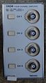
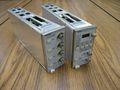
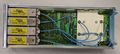
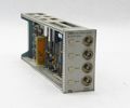
front view
-
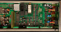
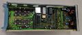
left side view
-
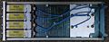
right side view
-
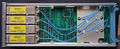
bottom view
-
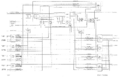
Block diagram
-
11A34V and 11T5H
-
11A34V and 11T5H
-
Prototype 11A34
-

Prototype 11A34
-
Prototype 11A34
-
Prototype 11A34
-
11A34V front
-

11A34V rear
-
11A34V left internal
-
11A34V right internal
-
11A34


Custom ICs used in the 11A34
| Page | Model | Part nos | Description | Designers | Used in |
|---|---|---|---|---|---|
| M377 | M377 | 165-2129-03 • 165-2089-06 • 155-2089-05 | amplifier | John Addis | 11A16 • 11A32 • 11A33 • 11A34 • 11A52 • 2245 • 2245A • 2247 • 2247A • 2252 • TDS410 • TDS420 • TDS460 • TDS520D • TDS540D • TDS580D • TDS680C • TDS684C • TDS714L • TDS724D • TDS754D • TDS784D |
| M474 | M474 | amplifier | John Addis • Ivan John Cousins | 11A32 • 11A34 |