11A52

The Tektronix 11A52 is a 600 MHz dual-channel plug-in for 11000-series and DSA600-series scopes. It has Tekprobe BNC connector inputs.
Key Specifications
| Bandwidth | DC to 600 MHz plus 100 MHz and 20 MHz BWL (Bandwidth Limit) filters |
|---|---|
| Number of Inputs | 2 |
| Rise time | 580 ps in 1 GHz mainframe such as the 11402, 11402A. 11403, 11403A, DSA601A, or DSA602A |
| Deflection | 1 mV to 10V per division in 1% calibrated steps |
| Input impedance | 50 Ω |
| Features |
|
Internals
Analog
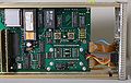
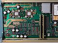
Each input channel has a separate 50 ohm attenuator containing, two X10 attenuators, a skin effect correction network, an AC coupling capacitor, a signal pickoff for the input protection network and a switch selecting the calibrator or signal input. In normal operation the calibrator signal to the attenuator is instead connected to ground.
The 11A52 uses custom Tektronix-made chips including the 155-0076-00 (M94 overload detector) and M377 amplifier chip.
The signal output of the attenuator feeds the + input of the M377 amplifier IC through a (blue) 50 ohm transmission line, one per input channel. The cable lengths set a standard delay per plugin. The M377's − input is connected to the ACVS (Analog Control Voltage System) output.
The (differential) display outputs of the two amplifiers are hard-wired in parallel and drive the mainframe’s 50 Ω per side input impedance. The same is true of the trigger outputs of the two amplifiers.
The version of the M377 used in the 11A52 has a 100 Ω output impedance per side so that two of them in parallel create a source impedance of 50 Ω per side.
Each M377 amplifier's nominal common-mode output voltage is zero whether enabled or not. When not enabled, each M377 differential output is exactly zero by design. This fact is used during calibration by the plugin’s firmware to determine the mainframe’s imbalance and compensate for it during normal operation.
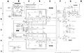
Each of the two channels has its own AUX output on dedicated pins of the plug-in interface connector:
| signal name | positive pin number | negative pin number |
|---|---|---|
| AUX 1 | B38 | B37 |
| AUX 2 | A36 | A35 |
See also the block diagram below.
Digital
The 11A32 and 11A34 and 11A52 were originally intended to use Intel 8052 microcontrollers. However, during development, the firmware swelled beyond that chip's 8192-byte maximum on-chip ROM size. Doug Haines found an alternate supplier of 8051-compatible chips (OKI Semiconductor) that offered a 16Kbyte on-chip ROM, and that's what the plug-ins wound up with. The finished code size wound up at about 14 KB.
In the 11A52, the digital output of the M94 overload detectors (one per channel) are received by the microprocessor. If overload is detected, software running in the microprocessor switches the input relay to remove the signal from the 50 Ω attenuator. This is in contrast to the 485, where the M94 directly controls the input relay.
During the 11A52's self-check, the M94 IC for each channel is tested. An analog switch injects test currents, positive and negative, into the summing junction at the input of each M94. The outputs are checked by the self-check software routine.
The 11A32 also contains a Dallas Semiconductor DS1220Y NVRAM storing last settings, calibration constants, and instrument serial number. The DS1220Y contains a battery with a typical life time of 20-30 years.
There is also an ACVS (Analog Control Voltage System) sample and hold module on a daughter board that generates the analog voltages needed for gain and offset, including error correction under microcontroller firmware control.
The microcontroller also provides the digital signals sent to the M377 amplifier, setting one of its six fixed gains, one of its three bandwidths, turning on or off its selected output, and each output's normal or invert state.
Digital mainframes do waveform manipulation (addition, subtraction, multiplication, etc.). Consequently only one 11A52 output is on at a time. Analog mainframes however allow more than one channel to be on at a time. This allows the plugin channels to be added or subtracted in the plugin.
Links
Pictures
-
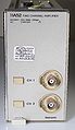
11A52 front
-
-
-
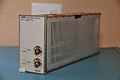
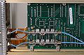
front panel connections
-
-
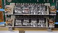
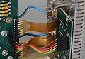
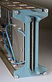
signal relays, top
-
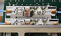
signal relays, bottom
-
-

-

-
-
-

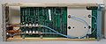
sample/hold modules
-
-
Input Attenuators Schematic
-
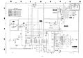
Kernel Schematic
-
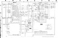
Analog Control and Signal Amps


Custom ICs used in the 11A52
| Page | Model | Part nos | Description | Designers | Used in |
|---|---|---|---|---|---|
| 155-0076-00 | M94 | 155-0076-00 | input protection and probe logic | John Addis • Wink Gross | 465 • 485 • 7A29 • 7A29P • 11A52 • 11A71 • 11A72 • SCD1000 |
| M377 | M377 | 165-2129-03 • 165-2089-06 • 155-2089-05 | amplifier | John Addis | 11A16 • 11A32 • 11A33 • 11A34 • 11A52 • 2245 • 2245A • 2247 • 2247A • 2252 • TDS410 • TDS420 • TDS460 • TDS520D • TDS540D • TDS580D • TDS680C • TDS684C • TDS714L • TDS724D • TDS754D • TDS784D |