D
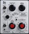
The Tektronix Type D is a differential amplifier plug-in for 500-series scopes. It was designed by Rodgers Jenkins.
Type D was the most sensitive plug-in of the original four. The bandwidth depends on the gain, ranging from 2 MHz at 50 mV/div to 300 kHz at 1 mV/div. There are two axes of sensitivity setting: a decade attenuator in front of a gain switch. This scheme would be reprised in Type W.
It displays the difference between two input signals, with a common-mode rejection ratio of 10,000. It has six tubes, on a shock-mounted subchassis to avoid microphonics.
Along with Types A, B, and C, Type D was introduced with the 531 and 535 in 1954.
At the time it was called Type 53D. It was briefly renamed 53D/54D in 1955 with the introduction of the 541 and 545. This quickly changed to 53/54D, and finally shortened to just "D" in 1959 with the introduction of the 5xxA scopes. Its final year in the catalog was 1968; it had been superseded by Type 1A6.
K, L, and T are tied for longest production life, at 16 years. B, D, and G are next at 15 years.
Lavoie Laboratories produced an unauthorized clone, the Lavoie LA-265-D.
Internals
Instruments below serial number 3462 used a pair of 5814 tubes at the input; later production used 12AU7's. These two tube types have different heater currents, and because the heaters are series-wired, you cannot switch from one type to the other without circuit modification.
Key Specifications
| Deflection | 1 mV/Div to 50 V/Div in 1–2–5-10-20-50 sequence and 1-10-100-1000 sequence |
|---|---|
| Input impedance | 1 MΩ // 47 pF (either input) |
| Bandwidth | 2 MHz with MV/CM MULTIPLIER set to 50; 300kHz with MV/CM MULTIPLIER set to 1 |
| CMRR | 10000:1 with MILLIVOLTS/CM set to 1, 1000:1 otherwise |
| Signal ranges |
| Range | Common mode dynamic range* |
|---|---|
| MILLIVOLTS/CM = 1 | ±2.5 V |
| MILLIVOLTS/CM = 10 | ±25 V |
| MILLIVOLTS/CM = 100 | ±250 V |
| MILLIVOLTS/CM = 1000 | ±500 V |
- In practice, Type D behaves well up to about +/–15V if the CM signal is either a brief excursion or a constant. If the CM varies slowly, DC shift in the input tubes will degrade CMRR.
Pictures
-
-
Front
-
Chassis
-
Rubber support for elimination of microphonics
-
Chassis bottom
-
Early Schematic
-
Late Schematic
-
Late Attenuators
-
Front View (vertical position knob not original)
Some Parts Used in the D
| Part | Part Number(s) | Class | Description | Used in |
|---|---|---|---|---|
| 12AU7 | 154-041 • 154-0041-00 • 154-0287-00 | Vacuum Tube (Dual Triode) | dual medium-μ triode | 104 • 104A • 122 • 160 • 161 • 162 • 181 • 190 • 310 • 310A • 316 • 317 • 3C66 • 502 • 502A • 507 • 511A • 512 • 516 • 517 • 517A • 524 • 526 • 535 • 536 • 545 • 545A • 545B • 547 • 549 • 555 • 561 • 564 • 570 • 575 • 581 • 581A • 585 • 585A • C • D • E • N • Q • Hickok 1825 • Keithley 660A |
| 5814 | 154-0054-00 • 154-0316-00 | Vacuum Tube (Double Triode) | twin medium-μ triode | D |
| 5879 | 154-0055-00 | Vacuum Tube (Pentode) | sharp-cutoff pentode | 112 • 512 • D • E • Hickok 1825 |


