4S1: Difference between revisions
No edit summary |
No edit summary |
||
| (13 intermediate revisions by 3 users not shown) | |||
| Line 1: | Line 1: | ||
{{Plugin Sidebar | {{Plugin Sidebar | ||
|manufacturer=Tektronix | |||
summary=Dual | |series=661 | ||
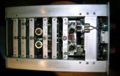
image=4S1 front.jpg | | |type=4S1 | ||
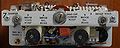
caption=4S1 front view image | |summary=Dual channel sampling plugin | ||
introduced=1962 |discontinued=(?) | | |image=4S1 front.jpg | ||
|caption=4S1 front view image | |||
manuals= | |introduced=1962 | ||
* [ | |discontinued=(?) | ||
|designers= | |||
|manuals= | |||
* [ | * [[Media:070-329.pdf|Tektronix 4S1 Manual (late)]] | ||
* [https://w140.com/tek_661_4s1_5t1_preliminary.pdf Tek 661 4S1 5T1 Preliminary Manual] | |||
* [[Media:Tek 4s1 cal outline.pdf|Tektronix 4S1 Calibration Outline]] (OCR) | |||
}} | }} | ||
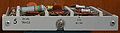
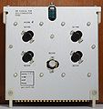
The '''Tektronix Type 4S1''' is a dual-trace [[sampling_oscilloscope|sampling]] unit for the [[661]]. | The '''Tektronix Type 4S1''' is a dual-trace [[sampling_oscilloscope|sampling]] unit for the [[661]]. | ||
The 4S1 was developed in 1961 and [[introduced in 1962]]. | The 4S1 was developed in 1961 and [[introduced in 1962]]. | ||
Each channel has a trigger | Each channel has a trigger pick-off, a [[delay line]], and a sampler. Specified rise time is 350 ps. | ||
The sampling pulses for each channel are generated by a step recovery diode. | The sampling pulses for each channel are generated by a step recovery diode. | ||
{{BeginSpecs}} | |||
{{Spec | Rise time | 350 ps }} | |||
{{Spec | Deflection | 2 mV/Div to 200 mV/Div, 1−2−5 }} | |||
{{Spec | Input impedance | 50 Ω }} | |||
{{EndSpecs}} | |||
''Please add'' | |||
==Description== | ==Description== | ||
| Line 22: | Line 31: | ||
The sampling pulses are fed to a sampling bridge made of four [[sampling diodes|GaAs diodes]]. | The sampling pulses are fed to a sampling bridge made of four [[sampling diodes|GaAs diodes]]. | ||
These diodes are fragile and exact replacements are hard to find. | These diodes are fragile and exact replacements are hard to find. | ||
They have however been successfully [[Sampling diodes|replaced by modern Schottky diodes]], e.g. Agilent HSMS-28x series. | |||
diodes | |||
=== Dual-trace and X-Y Modes === | === Dual-trace and X-Y Modes === | ||
The 4S1 has a dual-trace mode, where the A waveform and the B waveform | The 4S1 has a dual-trace mode, where the A waveform and the B waveform are both displayed in the | ||
are both displayed in the time domain at the same time with a single | time domain at the same time with a single trigger source and a single equivalent-time sweep rate. | ||
trigger source and a single equivalent-time sweep rate. Another mode | Another mode is called "A vert/B horiz". This mode is used in conjunction with an X-Y mode switch | ||
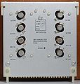
is called "A vert/B horiz". This mode is used in conjunction with | on the panel of the 661. The signals enter the 4S1 through [[GR-874 connector]]s on the front panel. | ||
an X-Y mode switch on the panel of the 661. The signals enter the 4S1 | |||
through [[GR-874 connector]]s on the front panel. | |||
=== Trigger Amplifier === | === Trigger Amplifier === | ||
The 4S1 uses an unusual trigger amplifier with two trigger signal paths. One path is for low frequencies, the other for high frequencies. | The 4S1 uses an unusual trigger amplifier with two trigger signal paths. | ||
One path is for low frequencies, the other for high frequencies. | |||
(A similar approach was also used in the main vertical signal path of the [[7A29]] several years later.) | (A similar approach was also used in the main vertical signal path of the [[7A29]] several years later.) | ||
From serial number 101 to 1349, the low frequency path starts with a 25 kΩ resistor that DC-couples the input signal to a | From serial number 101 to 1349, the low frequency path starts with a 25 kΩ resistor that DC-couples the input signal to a [[2N1429]] PNP emitter-follower stage. | ||
[[2N1429]] PNP emitter-follower stage. After that is a [[151-103]] NPN common-emitter. The high frequency path starts | After that is a [[151-103]] NPN common-emitter. The high frequency path starts with a trigger pick-off transformer on the input. | ||
with a trigger | The pick-off signal feeds a common-base amplifier that uses a [[2N700]] PNP transistor. | ||
that uses a [[2N700]] PNP transistor. | The low frequency and high frequency trigger paths meet at the trigger output of the 4S1. | ||
4S1. From there, the trigger signal passes through the 661, and into a [[5T1]] or [[5T3]]. 4S1 units with serial number | From there, the trigger signal passes through the 661, and into a [[5T1]] or [[5T3]]. | ||
1350 and up use a slightly less complex trigger amplifier circuit | |||
4S1 units with serial number 1350 and up use a slightly less complex trigger amplifier circuit, with a [[TA2333]] silicon NPN transistor amplifying the entire frequency range. | |||
=== Comparison with S-1 Sampling Heads === | === Comparison with S-1 Sampling Heads === | ||
The sampler board in the 4S1 is roughly equivalent to a pair of [[S-1|S- | The sampler board in the 4S1 is roughly equivalent to a pair of [[S-1|S-1 sampling heads]]. | ||
A short piece of RG | A short piece of RG-174 coax connects the 661 timing pulse coaxial connector to the [[SMB connector]] timing pulse input on the 4S1 sampler board. | ||
[[SMB connector]] timing pulse input on the 4S1 sampler board. This signal triggers | This signal triggers a blocking oscillator which drives a [[snap-off diode]], D2004, which generates the fast falling edge for the channel A and B sampling bridges. | ||
a blocking oscillator which drives a [[snap-off diode]], D2004, which generates the fast | The 4S1 uses [[7586|7586 nuvistor triodes]] as high-impedance buffers between the sampling bridge and the amplification that follows. | ||
falling edge for the channel A and | |||
follows. | |||
The 4S1 has a main chassis and sub-chassis that plug into it. | The 4S1 has a main chassis and sub-chassis that plug into it. | ||
A sub-chassis extension, part number [[012-069]], allows maintenance of the sub-chassis. | |||
sub-chassis. | |||
==Pictures== | ==Pictures== | ||
<gallery> | <gallery> | ||
Tek 4s1 front.jpeg | |||
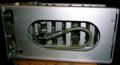
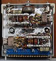
4s1_top.jpg|top view of 4S1 | 4s1_top.jpg|top view of 4S1 | ||
4s1_timing_pulse_connection.jpg|Coaxial interconnect (using [[Gremar connector]]s) from the timing plug-in goes through the mainframe, into the 4S1, and ends here, at the sampler. | 4s1_timing_pulse_connection.jpg|Coaxial interconnect (using [[Gremar connector]]s) from the timing plug-in goes through the mainframe, into the 4S1, and ends here, at the sampler. | ||
| Line 90: | Line 91: | ||
Tek 4s1 sampler rear.jpg|Sampler card | Tek 4s1 sampler rear.jpg|Sampler card | ||
</gallery> | </gallery> | ||
{{Parts|4S1}} | |||
[[Category:661 plugins]] | [[Category:661 plugins]] | ||
[[Category:Sampling plugins]] | [[Category:Sampling plugins]] | ||
[[Category:GR874]] | [[Category:GR874]] | ||
Latest revision as of 10:53, 20 July 2023

The Tektronix Type 4S1 is a dual-trace sampling unit for the 661. The 4S1 was developed in 1961 and introduced in 1962.
Each channel has a trigger pick-off, a delay line, and a sampler. Specified rise time is 350 ps. The sampling pulses for each channel are generated by a step recovery diode.
Key Specifications
| Rise time | 350 ps |
|---|---|
| Deflection | 2 mV/Div to 200 mV/Div, 1−2−5 |
| Input impedance | 50 Ω |
Please add
Description
Sampling Bridge
The sampling pulses are fed to a sampling bridge made of four GaAs diodes. These diodes are fragile and exact replacements are hard to find. They have however been successfully replaced by modern Schottky diodes, e.g. Agilent HSMS-28x series.
Dual-trace and X-Y Modes
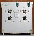
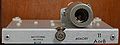
The 4S1 has a dual-trace mode, where the A waveform and the B waveform are both displayed in the time domain at the same time with a single trigger source and a single equivalent-time sweep rate. Another mode is called "A vert/B horiz". This mode is used in conjunction with an X-Y mode switch on the panel of the 661. The signals enter the 4S1 through GR-874 connectors on the front panel.
Trigger Amplifier
The 4S1 uses an unusual trigger amplifier with two trigger signal paths. One path is for low frequencies, the other for high frequencies. (A similar approach was also used in the main vertical signal path of the 7A29 several years later.)
From serial number 101 to 1349, the low frequency path starts with a 25 kΩ resistor that DC-couples the input signal to a 2N1429 PNP emitter-follower stage. After that is a 151-103 NPN common-emitter. The high frequency path starts with a trigger pick-off transformer on the input. The pick-off signal feeds a common-base amplifier that uses a 2N700 PNP transistor. The low frequency and high frequency trigger paths meet at the trigger output of the 4S1. From there, the trigger signal passes through the 661, and into a 5T1 or 5T3.
4S1 units with serial number 1350 and up use a slightly less complex trigger amplifier circuit, with a TA2333 silicon NPN transistor amplifying the entire frequency range.
Comparison with S-1 Sampling Heads
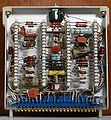
The sampler board in the 4S1 is roughly equivalent to a pair of S-1 sampling heads. A short piece of RG-174 coax connects the 661 timing pulse coaxial connector to the SMB connector timing pulse input on the 4S1 sampler board. This signal triggers a blocking oscillator which drives a snap-off diode, D2004, which generates the fast falling edge for the channel A and B sampling bridges. The 4S1 uses 7586 nuvistor triodes as high-impedance buffers between the sampling bridge and the amplification that follows.
The 4S1 has a main chassis and sub-chassis that plug into it. A sub-chassis extension, part number 012-069, allows maintenance of the sub-chassis.
Pictures
-

-
top view of 4S1
-
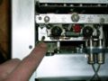
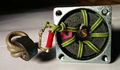
Coaxial interconnect (using Gremar connectors) from the timing plug-in goes through the mainframe, into the 4S1, and ends here, at the sampler.
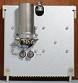
-
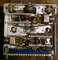
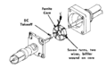
This is the sampler. The GaAs sampling diodes are arranged in a diamond shape and are directly connected to the socket from the delay line.
-
The delay line is a coil of coax going from the trigger pickoff to the sampler.
-
LF and HF trigger pickoff
-
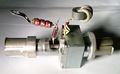
trigger pickoff
-
trigger pickoff
-
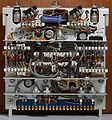
Bottom wiring
-
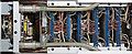
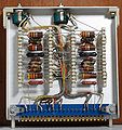
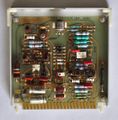
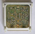
Dual trace card
-
Dual trace card
-
Dual trace card
-

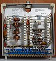
Inverter card
-
Inverter card
-
Inverter card
-
Memory card
-
Memory card
-
Memory card
-
Memory card front - solid state version
-
Memory card rear - solid state version
-
Amp card
-
Amp card
-

Amp card
-
Sampler card
-
Sampler card
-
Sampler card


Some Parts Used in the 4S1
| Part | Part Number(s) | Class | Description | Used in |
|---|---|---|---|---|
| 120-0304-00 | 120-0304-00 | Discrete component | inductor | 4S1 • 4S2 |
| 7308 | 154-0371-00 | Vacuum Tube (Dual Triode) | dual triode | 3S76 • 3S3 • 4S1 • 4S2A • 4S3 • S-311 |
| 7586 | 154-0306-00 | Vacuum Tube (Triode) | Nuvistor triode | M • 1A1 • 1A2 • 1A5 • 10A2 • 10A2A • 11B1 • 11B2A • 321 • 321A • 3A1 • 3A1S • 3A3 • 3A5 • 3A6 • 3A7 • 3A8 • 3A74 • 3S76 • 3T77 • 3T77A • 3B5 • 4S1 • 4S2 • 6R1 • 6R1A • 9A1 • 9A2 • 82 • 86 • S-311 |