561
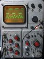
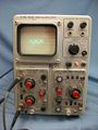
The Tektronix 561 is a 560-series scope that was introduced in 1961 and produced in various versions well into the 1970s. The designer of the 561 was Bob Shand.

Versions
Over its life, the 561 was actually a series of four very different scopes, plus the rack mount versions of each.
561
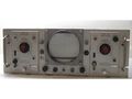
The original 561 and RM561 were introduced in 1961. Similar to the 560, also introduced in 1961, the 561 has a round CRT. It supports the 50, 60 and 70 series of plug-ins, with the highest system bandwidth of 4 MHz. The later 2- and 3- series plug-ins cannot be used in the 560 or 561, as they consume more power. Early, low power, plugins have the nylon guide on their backplane pointing into the plugin, while the later, higher power consuming, plugins have those nylon guides pointing outward. The outward pointing guide will bump into the chassis of a 560 or 561, preventing it from fully inserting. The 561A and all later 560 series scopes, with higher capability power supplies, have a hole in the chassis that allows the outward pointing nylon guide to clear, allowing full insertion.
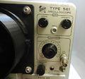
The 561 uses the T5032 CRT, which has a glass envelope. The 561 and later versions also had a front panel calibrator signal for calibrating the plugins to the mainframe. The 561 calibrator has 18 attenuation steps and can output a square wave with an amplitude of 200 μV to 100 V.
Early serial numbers of the 561 use a neon bulb (B633) in the -100 V regulator circuit, however, later versions (including the 561A and later) used a transistor. The modification for early units is documented at the end of the 561 manual and in the 040-288 Field Modification Instructions.
Documents Referencing 561
- (no results)
561A
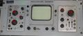
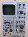
The short lived 561 was replaced by the 561A and the rack-mount version RM561A in 1962. The 561A were the highest selling model in the 560 series.
They introduced a revolutionary new CRT, the T5610, incorporating many “firsts” that would remain through most of Tek's analog scopes to follow – a rectangular faceplate allowing for a more compact CRT, and a ceramic CRT envelope which provided more mechanical precision than a blown glass tube. This also enabled the use of a separate face plate made from a flat glass panel that could have the graticule markings printed on the phosphor side of the faceplate, totally eliminating parallax errors, and allowing for better edge illumination.
The 561A was one of the mainframes offered for the Engine Analyzer System.
An RM561A with two custom plug-ins was incorporated (upside-down) as the standard display in the LINC computer.
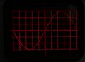
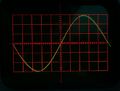
The Mod210C replaced the T5610 ceramic CRT with the T5032 glass CRT and an external graticule. The graticule illumination was changed to red and the BNC connectors of the scope and plugins were replaced with UHF connectors. The graticule has an engraved sinewave. A green light filter was added between the CRT and the graticule.
Documents Referencing 561A
| Document | Class | Title | Authors | Year | Links |
|---|---|---|---|---|---|
| Cliff moulton sensitive sampling plug-ins.pdf | Article | Sensitive Sampling Plug-ins and New Capabilities | Cliff Moulton | 1961 | Sampling • 561A • 3S76 • 3T77 • 567 |
561B
The 561B / RM561B were introduced in 1969. The 561B uses the same 560-series plug-ins used by the 561A. The 561B models actually provided no performance improvements over the 561A, with the change being limited to all solid state design, including the HV rectifiers. While this change improves reliability of the mainframe, Tektronix never produced fully solid state amplifier or non-sampling timebase plug-ins for the 560 Series.
Documents Referencing 561B
| Document | Class | Title | Authors | Year | Links |
|---|---|---|---|---|---|
| 070-0890-00.pdf | Manual | Engine Analyzer System | 1968 | Engine Analyzer System • 561B • 564B • 3A74 • 2B67 • 015-0108-00 | |
| Tekscope 1969 V1 N1 Feb 1969.pdf | Article | An Extended Value | John Durecka | 1969 | 561B • 564B |
| Tekscope 1969 V1 N2 Apr 1969.pdf | Article | A New Insight Into Reciprocating Machinery | Bill Verhoef | 1969 | Engine Analyzer System • 3A74 • 561B • 564B |
Patents that may apply to 561B
| Page | Title | Inventors | Filing date | Grant date | Links |
|---|---|---|---|---|---|
| Patent US 3453403A | Power selection device | Eldon Hoffman | 1966-08-18 | 1969-07-01 | 115 • 140 • 141 • 141A • 144 • 145 • 146 • 147 • 148 • 149 • 149A • 230 • 284 • 286 • 453 • 454 • 491 • 520A • 521A • 522 • 545B • 547 • 556 • 561B • 564B • 568 • 576 • 611 • 647A • 2101 • 2601 • 4501 • 5030 • R5030 • 5031 • R5031 • 7503 • 7504 • 7704 • 7704A • 7904 • R7903 |
561S
A special 561S was introduced as a special product, modified from a 561A. It did not appear in any Tek catalog. With special modified amplifier and time base (3A1S and 3B1S), and a special CRT (T5033), it achieved a 25 MHz system bandwidth, which is 2.5 times the bandwidth of a 561A.
The 3A1S and 3B1S were the only plug-ins that could be used in the 561S because the T5033 CRT has higher deflection sensitivity than the CRT used in the 561, 561A, and 561B. The vertical deflection sensitivity of the T5033 is 11.7 V/cm. The 561A has the T561 CRT which has a vertical deflection sensitivity of 19.5 V/cm.
The higher bandwidth of the 561S came at the expense of trading off some of the advances gained in the original 561A. The CRT is a conventional glass envelope, without internal graticule. Also, the scale was reduced from 8 × 10 divisions to 6 × 10. The 561S has no post-deflection acceleration, and a CRT cathode voltage of -3,300 V, like the other 561 models.
Documents Referencing 561S
- (no results)
Plugin Compatibility
The popular 60 and 70 series plug-ins were later given a “2A, 2B, 3A, or 3B” prefix. The highest bandwidth plug-ins gave a system bandwidth of 10 MHz when used in the 561A and 561B.
The 561A, RM561A, 561B, and RM561B are compatible with all of the 2 and 3-series plugins that Tektronix made. The 561 and RM561 have limited compatibility with some 3-series plugins, mainly due to the CRT circuit. For plugins such as the 3B1 and 3B3 time bases there are issues with the blanking and intensified sweep. The 561A and subsequent models used a dual-secondary winding transformer in the CRT power supply, with one winding used in an intensifying pulse circuit which the original 561 lacked. Other 3-series plugins may be used in the original 561 with some modifications – for example, to use a 3A74 4-channel vertical plugin in a 561 sn101 to 579, the +6 V unregulated supply needs to be disconnected from both plugin connectors (pin 18). Later 561's with sn580 and higher already had this change implemented. More information regarding the use of 3-series plugins and the required modifications (if available) can be found in the Tektronix 561 Instrument Reference Book (IRB).
Key Specifications
| — 561 — | |
| Bandwidth | DC to 4 MHz (with 3A75, may vary with other plug-ins) |
| Rise time | 0.09 μs |
| Power Consumption | 185 W with 72 & 67 plug-ins |
| — 561A & 561B — | |
| Bandwidth | DC to 15 MHz (with 3A5, may vary with other plug-ins) |
| Rise time | 0.024 μs |
| Power Consumption | 178 W with plug-ins |
| — 561S — | |
| Bandwidth | DC to 25 MHz (with 3A1S, may vary with other plug-ins) |
| Rise time | 0.014 μs |
| Power Consumption | 210 W to 240 W with plug-ins |
| — all — | |
| Line Voltage | 105-125/210-250 VAC ±10%, selected via primary voltage selector and voltage range selector switches, 50 Hz to 60 Hz. |
| Thermal Protection | Automatic resetting thermal cutout, in case internal temperature exceeds safe operating level |
| Anode Potential | 3.5 kV |
| Screen Area | 8 cm × 10 cm ( 561S: 6 cm x 10 cm ) |
| Construction | Aluminum alloy chassis. Anodized front panel |
Links
Pictures
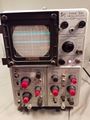
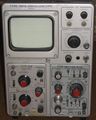
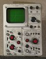
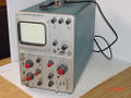
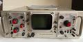
561
-
561 with Camera Mount
-
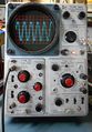
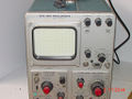
561 with Round CRT and External Graticule
-
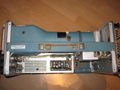
561 Left Side
-
561 Right Side
-
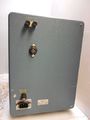
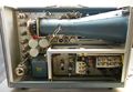
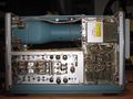
561 Rear
-
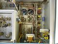
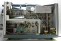
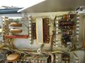
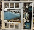
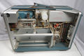
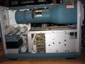
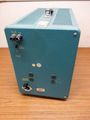
561 Power Supply
-
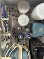
561 Power Supply Tubes
-
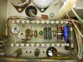
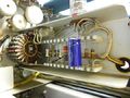
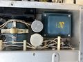
Low Voltage Power Supply
-
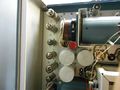
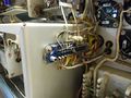
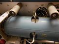
High Voltage Power Supply
-
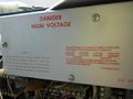
High Voltage Power Supply Cover
-
Plugin Connector
-
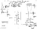
Calibrator Circuit
-
Calibrator
-
Deflection Plate Connections
-

CRT Socket


RM561
-
RM561 with wrong CRT Bezel plus Two Type 75 (3A75) Amplifier Plugins
-
-
RM561 Inside Top
-
RM561 Inside Top Right
-
RM561 Inside Top Left


561A
-
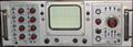
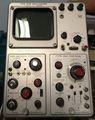
561A Front
-
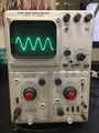
561A with Trace
-

561A Left Front
-
-
Guernsey-made 561A Rear
-
561A (plug-in missing tubes)
-
561A Right Internals
-

561A Low Voltage Power Supply
-
561A CRT Circuit


561A/MOD210C
-
561A with Mod210C Power Off
-
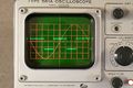
561A with Mod210C Graticule at 100% & Showing Signal
-
561A with Mod210C Graticule at Right
-
561A with Mod210C Comparing Sinewave Signal to the Engraved Signal


RM561A
-

-
-

RM561A Top Inside
-

RM561A in LINC Computer Console
-


561B
-
561B Front Right
-
561B Front Upper
-

561B Front Left
-

561B Rear
-
-
561B Trace
-
561B Left Inside
-
561B Right Inside
-
561B Top Inside


R561B
-
R561B Front

561S
-
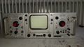
561S Front
-

-
561S Rear
-


Components
Some Parts Used in the 561
Some Parts Used in the 561A
Some Parts Used in the 561B
| Part | Part Number(s) | Class | Description | Used in |
|---|---|---|---|---|
| 120-0575-00 | 120-0575-00 | Discrete component | power transformer | 561B |
| 2N3739 | 151-0201-00 | Discrete component | Silicon NPN power transistor | 013-002 • 106 • 4501 • 561B • R561B • 564B • R564B • 568 • 7503 • 7504 |
| T5611 | 154-0531-00 • 154-0531-01 • 154-0531-02 • 154-0531-03 • 154-0613-00 • 154-0613-01 • 154-0613-02 • 154-0613-03 • 154-0614-00 • 154-0614-01 • 154-0614-02 • 154-0614-03 | CRT | ceramic CRT | 561A • 561B • 567 • 568 |