568: Difference between revisions
(template change) |
No edit summary |
||
| (25 intermediate revisions by 3 users not shown) | |||
| Line 1: | Line 1: | ||
{{Oscilloscope Sidebar | | {{Oscilloscope Sidebar | ||
|manufacturer=Tektronix | |||
summary=Sampling scope | | |series=560-series scopes | ||
image= | |model=568 | ||
caption=Tektronix 568 | |summary=Sampling scope | ||
introduced=1967 | | |image=568_1.JPG | ||
discontinued= | |caption=Tektronix 568 front, with [[3S6]] and [[3T6]] plugins | ||
|introduced=1967 | |||
manuals= | |discontinued=1987 | ||
* [http://bama.edebris.com/download/tek/568/568.djvu | |designers= | ||
* [ | |manuals= | ||
* [[Media:070-0596-00.pdf|Tektronix 568 Manual]]<small><br />Alternate: [http://bama.edebris.com/download/tek/568/568.djvu DjVu @ BAMA]</small> | |||
* [[Media:Tek readout oscilloscopes 1968 catalog.pdf|"Digital Readout Introduction" in 1968 Catalog]] | |||
* [[Media:Tek 568 fcp jan 1967.pdf]] | |||
}} | }} | ||
The 568 is a [[sampling oscilloscope]] | The '''Tektronix 568''' is a [[sampling oscilloscope]], [[introduced in 1967]], which takes 3S- and 3T-series plug-ins. | ||
Although it was intended to be used for sampling, it can also be used with non-sampling plug-ins of the 3A and 3B series. | Although it was intended to be used for sampling, | ||
it can also be used with non-sampling plug-ins of the 3A and 3B series. | |||
Like the [[561]] and [[564]], the 568 does not contain vertical or horizontal amplifiers. | Like the [[561]] and [[564]], the 568 does not contain vertical or horizontal amplifiers. | ||
The plug-ins directly drive the deflection plates. | |||
The 568 has multi-pin connectors on its rear panel that are routed to multi-pin connectors on the plug-ins. | |||
This is to support external control and measurement using, for example, a [[230]] and [[241]]. | |||
The typical cable for connecting the [[568]] to the [[230]] is the [[012-0119-01]]. | |||
Two sampling heads can be interfaced directly to the 568 using the [[012-0130-00]] cable, or | Two sampling heads can be interfaced directly to the 568 using the [[012-0130-00]] cable, or | ||
multiple sampling heads can be interfaced using an multiplexer such as the [[286]], [[287]], | multiple sampling heads can be interfaced using an multiplexer such as the [[286]], [[287]], | ||
or [[R288]]. | or [[R288]]. | ||
CRT was the [[T5032]]-2-1 ([[154-0454-00]]) or [[T5611]]-2-1 ([[154-0613-01]]). | |||
The 568 was distributed as a self-contained instrument and also | The 568 was distributed as a self-contained instrument and also | ||
as a component of integrated test and measurement systems | as a component of integrated test and measurement systems | ||
such as the [[S-3100]]. | such as the [[S-3100]]. | ||
As a part of the test and measurement systems, | |||
the 568 was sold at least until 1986. | |||
A modification, 708P, was available for the 568 to give it a head multiplexer instead of a CRT. Head multiplexer is similar with [[286]] | |||
{{BeginSpecs}} | |||
{{Spec | Bandwidth | sampling, DC to 14,5 GHz (with [[3S2]] and [[S-4]] head, may vary with other plug-ins);<br />realtime, DC to 15 MHz (with [[3A5]], may vary with other plug-ins) }} | |||
{{Spec | Rise time | sampling, 25 ps;<br />realtime, 24 ns }} | |||
{{Spec | Acceleration voltage | 3.5 kV}} | |||
{{Spec | Screen Area | 8 cm × 10 cm }} | |||
{{Spec | Calibrator | 0.5 V , 5 V (p-p) into 1 MΩ, 50mV, 0.5 V (p-p) into 50 Ω, selectable 1 kHz( -50 % / +100%)and 100 kHz (0.05 %), ( Serial B150629 below 20 kHz instead 100 kHz)}} | |||
{{Spec | Screen Area | 8 cm × 10 cm }} | |||
{{Spec | Power | 100/115/124/200/230/248 V<sub>AC</sub> ±10%, selected via primary voltage selector and voltage range selector switches, 48 Hz to 66 Hz; max 210 W with plug-ins }} | |||
{{Spec | Thermal Protection | Automatic resetting thermal cutout, in case internal temperature exceeds safe operating level }} | |||
{{Spec | Construction | Aluminum alloy chassis. Anodized front panel}} | |||
{{EndSpecs}} | |||
==Links== | |||
* [http://www.museum-nt.de/objekte/tek_568.html Tek 568 @ museum-nt.de] | |||
{{Documents|Link=568}} | |||
== | ==See Also== | ||
[[ | * [[S-3110]] | ||
==Pictures== | ==Pictures== | ||
<gallery> | <gallery> | ||
568_1.JPG |568 front | |||
230_568_0.JPG |230 and 568 measuring risetime | |||
568_rear.JPG |568 rear | |||
568_i_top.JPG |568 top inside | |||
568_i_bot.JPG |568 bottom inside | |||
568 708p front.jpg |568 Mod 708P front | |||
568 708p switching.jpg|568 Mod 708P head multiplexer circuitry | |||
568 708p rear.jpg |568 Mod 708P rear | |||
</gallery> | </gallery> | ||
| Line 41: | Line 73: | ||
[[Category:560 series scopes]] | [[Category:560 series scopes]] | ||
[[Category:Sampling scopes]] | [[Category:Sampling scopes]] | ||
Latest revision as of 06:42, 8 November 2024
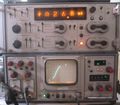
The Tektronix 568 is a sampling oscilloscope, introduced in 1967, which takes 3S- and 3T-series plug-ins. Although it was intended to be used for sampling, it can also be used with non-sampling plug-ins of the 3A and 3B series.
Like the 561 and 564, the 568 does not contain vertical or horizontal amplifiers. The plug-ins directly drive the deflection plates. The 568 has multi-pin connectors on its rear panel that are routed to multi-pin connectors on the plug-ins. This is to support external control and measurement using, for example, a 230 and 241. The typical cable for connecting the 568 to the 230 is the 012-0119-01.
Two sampling heads can be interfaced directly to the 568 using the 012-0130-00 cable, or multiple sampling heads can be interfaced using an multiplexer such as the 286, 287, or R288.
CRT was the T5032-2-1 (154-0454-00) or T5611-2-1 (154-0613-01).
The 568 was distributed as a self-contained instrument and also as a component of integrated test and measurement systems such as the S-3100. As a part of the test and measurement systems, the 568 was sold at least until 1986.
A modification, 708P, was available for the 568 to give it a head multiplexer instead of a CRT. Head multiplexer is similar with 286
Key Specifications
| Bandwidth | sampling, DC to 14,5 GHz (with 3S2 and S-4 head, may vary with other plug-ins); realtime, DC to 15 MHz (with 3A5, may vary with other plug-ins) |
|---|---|
| Rise time | sampling, 25 ps; realtime, 24 ns |
| Acceleration voltage | 3.5 kV |
| Screen Area | 8 cm × 10 cm |
| Calibrator | 0.5 V , 5 V (p-p) into 1 MΩ, 50mV, 0.5 V (p-p) into 50 Ω, selectable 1 kHz( -50 % / +100%)and 100 kHz (0.05 %), ( Serial B150629 below 20 kHz instead 100 kHz) |
| Screen Area | 8 cm × 10 cm |
| Power | 100/115/124/200/230/248 VAC ±10%, selected via primary voltage selector and voltage range selector switches, 48 Hz to 66 Hz; max 210 W with plug-ins |
| Thermal Protection | Automatic resetting thermal cutout, in case internal temperature exceeds safe operating level |
| Construction | Aluminum alloy chassis. Anodized front panel |
Links
Documents Referencing 568
| Document | Class | Title | Authors | Year | Links |
|---|---|---|---|---|---|
| Service Scope 43 Apr 1967.pdf | Article | New From Tektronix, Inc. In 1967 | 1967 | 568 • 230 • 454 • 647A • C-40 • 1A4 • 1A5 • 3L5 • 200-1 | |
| Service Scope 53 Dec 1968.pdf | Article | Digital Systems Come Of Age | John Bowne | 1968 | 3T5 • 3T6 • 3S5 • 3S6 • S-1 • S-2 • S-3 • S-4 • 568 • 230 |
| Service scope dec 1968 ocr.pdf | Article | Digital Systems Come of Age | John Bowne | 1968 | 3T5 • 3T6 • 3S5 • 3S6 • S-1 • S-2 • S-3 • S-4 • 568 • 230 • 240 • 241 • 250 |
| Service Scope 52 Oct 1968.pdf | Article | The State of the Art in Sampling | Al Zimmerman | 1968 | S-1 • S-2 • S-3 • S-4 • S-50 • S-51 • 285 • 3S1 • 3S2 • 3S5 • 3S6 • 3T2 • 3T5 • 3T6 • 3T77A • 568 • 230 |
| Tekscope 1970 V2 N4 Aug 1970.pdf | Article | Automated Measurement Systems | 1970 | S-3150 • 568 • 230 • S-3110 • 241 • 240 | |
| Tekscope 1971 V3 N1 Jan 1971.pdf | Article | Short Pulse Technique of Adjusting Wideband Amplifiers | Carl Battjes | 1971 | 7A16 • 109 • 568 • 230 |
| Tekscope 1971 V3 N5 Sep 1971.pdf | Article | The R1340 Data Coupler | 1971 | R1340 • 568 • 3S6 • 3T6 |
See Also
Pictures
-
568 front
-
230 and 568 measuring risetime
-
568 rear
-
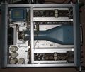
568 top inside
-
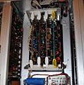
568 bottom inside
-
568 Mod 708P front
-
568 Mod 708P head multiplexer circuitry
-
568 Mod 708P rear


