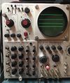
M: Difference between revisions
No edit summary |
No edit summary |
||
| Line 1: | Line 1: | ||
{{Plugin Sidebar | | {{Plugin Sidebar | ||
|manufacturer=Tektronix | |||
summary=20 MHz quad channel amplifier| | |series=500-series scopes | ||
image=Type m front.jpg | | |type=Type M | ||
caption=Type M front view| | |summary=20 MHz quad-channel amplifier | ||
introduced=1962 | | |image=Type m front.jpg | ||
discontinued=1973 | | |caption=Type M front view | ||
|introduced=1962 | |||
manuals= | |discontinued=1973 | ||
|designers=Oz Svehaug;Glenn Parks | |||
|manuals= | |||
* [[Media:070-295.pdf|Tektronix Type M Manual]] (OCR) | |||
* [[Media:tek_type_m_fcp.pdf|Tektronix Type M Factory Calibration Procedure]] (OCR) | |||
* [[Media:070-295.pdf|Tektronix Type M Manual ( | * [[Media:Tek type m cal outline.pdf|Tektronix Type M Calibration Outline]] (OCR) | ||
* [[Media:tek_type_m_fcp.pdf|Tektronix Type M Factory Calibration Procedure ( | <small> | ||
* [[Media:Tek type m cal outline.pdf|Tektronix Type M Calibration Outline ( | '''Alternate copies''' | ||
* [https://bama.edebris.com/manuals/tek/m/ Tektronix Type M Manual]] (DjVu @ BAMA) | |||
</small> | |||
}} | }} | ||
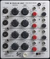
The '''Tektronix Type M''' is a four-channel plug-in for [[500-series scopes]]. | The '''Tektronix Type M''' is a four-channel plug-in for [[500-series scopes]] that was [[introduced in 1962]], along with the [[O|Type O]], and dropped after 1972. | ||
It was designed by [[Oz Svehaug]] and [[Glenn Parks]]. | It was designed by [[Oz Svehaug]] and [[Glenn Parks]]. | ||
Early versions had [[UHF connector]]s, later versions have [[BNC connector]]s for the inputs. | |||
{{ | {{BeginSpecs}} | ||
{{Spec | Bandwidth | DC to 20 MHz }} | |||
{{Spec | Rise time | 17 ns }} | |||
{{Spec | Deflection | 20 mV/div to 10 V/div, 1–2–5 }} | |||
Each channel can be AC or DC coupled, inverted or straight, or disabled entirely. | {{Spec | Modes | Each channel can be AC or DC coupled, inverted or straight, or disabled entirely. The enabled channels can operate in CHOP or ALT mode. }} | ||
The enabled channels can operate in CHOP or ALT mode. | {{EndSpecs}} | ||
==Internals== | ==Internals== | ||
Each input goes through a step attenuator, | Each input goes through a step attenuator, is clamped by a neon bulb, and then is fed to the grid of a cathode follower made with a [[7586]] Nuvistor tube. | ||
is clamped by a neon bulb, | |||
and then is fed to the grid of a cathode follower | |||
made with a [[7586]] Nuvistor tube. | |||
Next, the signal goes to a PNP differential amplifier. | Next, the signal goes to a PNP differential amplifier. | ||
Diodes in series with the collector signal | Diodes in series with the collector signal of this differential amplifier are used for input channel switching. | ||
of this differential amplifier are used for input channel switching. | An internal differential signal bus connects the switched outputs of each of the input channels and feeds the signal to the output amplifier, | ||
An internal differential signal bus connects | |||
the switched outputs of each of the input channels | |||
and feeds the signal to the output amplifier, | |||
which drives pins 1 and 3 of the [[500-series plug-in connector]]. | which drives pins 1 and 3 of the [[500-series plug-in connector]]. | ||
The output amplifier is two [[12AU6]] pentodes | The output amplifier is two [[12AU6]] pentodes connected as a differential amplifier, | ||
connected as a differential amplifier, | followed by a [[12AT7]] dual triode acting as a cathode follower to drive the output with a relatively low impedance. | ||
followed by a [[12AT7]] dual triode acting | |||
as a cathode follower to drive the output | |||
with a relatively low impedance. | |||
==Pictures == | ==Pictures == | ||
<gallery> | <gallery> | ||
Type_m_front.jpg|Late Type M Front view | Type_m_front.jpg|Late Type M Front view | ||
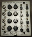
Type_m_left.jpg|Late Type M Left view | Type_m_left.jpg|Late Type M Left view | ||
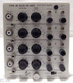
Type_m_right.jpg|Late Type M Right view | Type_m_right.jpg|Late Type M Right view | ||
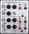
Tek_early_m_front.jpg|Early Type M Front | Tek_early_m_front.jpg|Early Type M Front | ||
| Line 64: | Line 54: | ||
Tek m 501 6.jpg | Tek m 501 6.jpg | ||
Tek m mod210d.jpg|Type M Mod 210D | Tek m mod210d.jpg|Type M Mod 210D | ||
Type m chan switching low sn.png|Channel Switching Schematic, | Type m chan switching low sn.png|Channel Switching Schematic, SN 824 and below | ||
Type m chan switching sn 825-up.png|Channel Switching Schematic, | Type m chan switching sn 825-up.png|Channel Switching Schematic, SN 825 and above | ||
Type m 4 chan switched amp low sn.png|Four Channel Switched Amplifier Schematic, | Type m 4 chan switched amp low sn.png|Four Channel Switched Amplifier Schematic, SN 2759 and below | ||
Type m 4 chan switched amp sn 2760-up.png|Four Channel Switched Amplifier Schematic, | Type m 4 chan switched amp sn 2760-up.png|Four Channel Switched Amplifier Schematic, SN 2760 and above | ||
tek_type_m_in_556.jpg|Type M in [[556]] | tek_type_m_in_556.jpg|Type M in [[556]] | ||
</gallery> | </gallery> | ||
Revision as of 08:33, 22 February 2022
The Tektronix Type M is a four-channel plug-in for 500-series scopes that was introduced in 1962, along with the Type O, and dropped after 1972. It was designed by Oz Svehaug and Glenn Parks.
Early versions had UHF connectors, later versions have BNC connectors for the inputs.
Key Specifications
| Bandwidth | DC to 20 MHz |
|---|---|
| Rise time | 17 ns |
| Deflection | 20 mV/div to 10 V/div, 1–2–5 |
| Modes | Each channel can be AC or DC coupled, inverted or straight, or disabled entirely. The enabled channels can operate in CHOP or ALT mode. |
Internals
Each input goes through a step attenuator, is clamped by a neon bulb, and then is fed to the grid of a cathode follower made with a 7586 Nuvistor tube. Next, the signal goes to a PNP differential amplifier. Diodes in series with the collector signal of this differential amplifier are used for input channel switching. An internal differential signal bus connects the switched outputs of each of the input channels and feeds the signal to the output amplifier, which drives pins 1 and 3 of the 500-series plug-in connector. The output amplifier is two 12AU6 pentodes connected as a differential amplifier, followed by a 12AT7 dual triode acting as a cathode follower to drive the output with a relatively low impedance.
Pictures
-
Late Type M Front view
-
Late Type M Left view
-
Late Type M Right view
-
Early Type M Front
-
Early Type M Left
-
Early Type M Right
-
-
-
-
-
-
-
Type M Mod 210D
-
Channel Switching Schematic, SN 824 and below
-
Channel Switching Schematic, SN 825 and above
-
Four Channel Switched Amplifier Schematic, SN 2759 and below
-
Four Channel Switched Amplifier Schematic, SN 2760 and above
-
Type M in 556
Some Parts Used in the M
| Part | Part Number(s) | Class | Description | Used in |
|---|---|---|---|---|
| 12AT7 | 154-0039-00 | Vacuum Tube (Dual Triode) | dual high-gain triode | 161 • 180 • 310 • 310A • 315 • 316 • 360 • 502 • 502A • 511A • 512 • 513 • 513D • 514 • 514AD • 514D • 516 • 524 • 529 • RM529 • 544 • 546 • 547 • 556 • 565 • 570 • 3A2 • 75 • 3A75 • 1M1 • A • B • C • G • H • K • L • ML • M • N • K • R • S • Z • Keithley 610B |
| 12AU6 | 154-0040-00 | Vacuum Tube (Pentode) | RF pentode | 81 • 112 • 1L10 • 1L20 • 1L60 • 3L10 • 512 • 556 • 575 • 545 • 547 • 549 • 581 • 585 • A • B • C • G • K • H • L • ML • M • N • O • R • S • Z |
| 7586 | 154-0306-00 | Vacuum Tube (Triode) | Nuvistor triode | M • 1A1 • 1A2 • 1A5 • 10A2 • 10A2A • 11B1 • 11B2A • 321 • 321A • 3A1 • 3A1S • 3A3 • 3A5 • 3A6 • 3A7 • 3A8 • 3A74 • 3S76 • 3T77 • 3T77A • 3B5 • 4S1 • 4S2 • 6R1 • 6R1A • 9A1 • 9A2 • 82 • 86 • S-311 |

