7A14: Difference between revisions
No edit summary |
No edit summary |
||
| Line 5: | Line 5: | ||
|summary=120 MHz current probe amplifier | |summary=120 MHz current probe amplifier | ||
|image=Tek 7a14 de.jpg | |image=Tek 7a14 de.jpg | ||
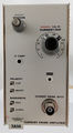
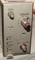
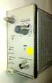
|caption=7A14 | |caption=Tektronix 7A14 | ||
|introduced=1969 | |introduced=1969 | ||
|discontinued=1975 | |discontinued=1975 | ||
| Line 14: | Line 14: | ||
The '''Tektronix 7A14''' is a 120 MHz current probe amplifier vertical plug-in for [[7000-series scopes|7000 series]], intended to be used with passive current probes such as the [[P6021]] and [[P6022]]. | The '''Tektronix 7A14''' is a 120 MHz current probe amplifier vertical plug-in for [[7000-series scopes|7000 series]], intended to be used with passive current probes such as the [[P6021]] and [[P6022]]. | ||
The [[P6019]] and [[P6020]] also work but with reduced bandwidth flatness, and the P6019 needs | The [[P6019]] and [[P6020]] also work but with reduced bandwidth flatness, and the [[P6019]] needs a [[131-0750-00]] adapter (s.b.) | ||
The 7A14 is one of the original plug-in modules [[introduced in 1969|introduced at the start of the 7000 series in 1969]]. | The 7A14 is one of the original plug-in modules [[introduced in 1969|introduced at the start of the 7000 series in 1969]]. | ||
| Line 25: | Line 25: | ||
==Operation== | ==Operation== | ||
In the 7A14, the ring around the input [[BNC connector]] that is used to identify ×10/×100 probes on voltage probes serves the purpose of detecting the difference between the P6021 and P6022 probes, and switching in appropriate gain and frequency compensation. | In the 7A14, the ring around the input [[BNC connector]] that is used to identify ×10/×100 probes on voltage probes serves the purpose of detecting the difference between the [[P6021]] and [[P6022]] probes, and switching in appropriate gain and frequency compensation. | ||
The P6021 shorts this ring to ground, directly switching three relays connected to −15 V internally. When connecting a [[P6019]] probe, the ring must also be grounded but the probe connector does not have the matching pin. The [[131-0750-00]] adapter solves this problem. | The [[P6021]] shorts this ring to ground, directly switching three relays connected to −15 V internally. When connecting a [[P6019]] probe, the ring must also be grounded but the probe connector does not have the matching pin. The [[131-0750-00]] adapter solves this problem. | ||
The front panel gain and low frequency compensation screwdriver adjustments do not differentiate between the P6021 or P6022 probes, i.e. swapping probes requires re-adjustment. Note that the low frequency compensation adjustment has a large impact on waveform accuracy and requires careful adjustment to a certain slope when using a 1 kHz calibrator signal as discussed in the manual. | The front panel gain and low frequency compensation screwdriver adjustments do not differentiate between the [[P6021]] or [[P6022]] probes, i.e. swapping probes requires re-adjustment. Note that the low frequency compensation adjustment has a large impact on waveform accuracy and requires careful adjustment to a certain slope when using a 1 kHz calibrator signal as discussed in the manual. | ||
==Links== | ==Links== | ||
| Line 35: | Line 35: | ||
==Internals== | ==Internals== | ||
The 7A14 uses twelve Tek-made [[miniature relays]] that can be a service issue. | The 7A14 uses twelve Tek-made [[miniature relays]] that can be a service issue. | ||
| Line 59: | Line 58: | ||
==Pictures== | ==Pictures== | ||
<gallery> | <gallery> | ||
Tek 7a14 1.jpg | Tek 7a14 1.jpg | ||
| Line 72: | Line 70: | ||
</gallery> | </gallery> | ||
==Measurement examples== | |||
Current through a 50 Ω resistor measured with [[P6021]] (top trace) compared to the voltage across the resistor (bottom trace). Measured with [[7854]] and [[7A26]] illustrating the low frequency limitation of the different probe termination methods. In the 10 mA/mV setting of the termination box the gain of the scope's vertical amplifier is insufficient to scale the current trace to the same nominal size as the voltage trace. <br /> | Current through a 50 Ω resistor measured with [[P6021]] (top trace) compared to the voltage across the resistor (bottom trace). Measured with [[7854]] and [[7A26]] illustrating the low frequency limitation of the different probe termination methods. In the 10 mA/mV setting of the termination box the gain of the scope's vertical amplifier is insufficient to scale the current trace to the same nominal size as the voltage trace. <br /> | ||
The signal shown is a squarewave from a [[PG501]] @ 4 V<sub>p-p</sub> into 50 Ω = 80 mA<sub>p-p</sub>. | The signal shown is a squarewave from a [[PG501]] @ 4 V<sub>p-p</sub> into 50 Ω = 80 mA<sub>p-p</sub>. | ||
Revision as of 22:02, 2 December 2023

The Tektronix 7A14 is a 120 MHz current probe amplifier vertical plug-in for 7000 series, intended to be used with passive current probes such as the P6021 and P6022.
The P6019 and P6020 also work but with reduced bandwidth flatness, and the P6019 needs a 131-0750-00 adapter (s.b.)
The 7A14 is one of the original plug-in modules introduced at the start of the 7000 series in 1969.
Key Specifications
| Deflection | 1 mA/Div to 1 A/Div in 1–2–5 sequence |
|---|---|
| Bandwidth | P6021: 25 Hz – 50 MHz (55 MHz in 79xx) P6022: 250 Hz – 105 MHz (120 MHz in 79xx, 80 MHz in 76xx) |
| Features | Bandwidth limiting switch (20 MHz), polarity switch |
Operation
In the 7A14, the ring around the input BNC connector that is used to identify ×10/×100 probes on voltage probes serves the purpose of detecting the difference between the P6021 and P6022 probes, and switching in appropriate gain and frequency compensation. The P6021 shorts this ring to ground, directly switching three relays connected to −15 V internally. When connecting a P6019 probe, the ring must also be grounded but the probe connector does not have the matching pin. The 131-0750-00 adapter solves this problem.
The front panel gain and low frequency compensation screwdriver adjustments do not differentiate between the P6021 or P6022 probes, i.e. swapping probes requires re-adjustment. Note that the low frequency compensation adjustment has a large impact on waveform accuracy and requires careful adjustment to a certain slope when using a 1 kHz calibrator signal as discussed in the manual.
Links
Documents Referencing 7A14
| Document | Class | Title | Authors | Year | Links |
|---|---|---|---|---|---|
| Tekscope 1969 V1 N5 Oct 1969.pdf | Article | Introducing the New Generation | 1969 | 7000-series scopes • 7504 • 7704 • 7A11 • 7A12 • 7A13 • 7A14 • 7A16 • 7A22 • 7S11 • 7M11 • 7B50 • 7B51 • 7B70 • 7B71 • 7T11 • R5030 • 7000 series readout system • Miniature relays • Cam switches • Industrial Design • T7500 • T7700 • P6052 • P6053 • C-50 • C-51 • 204-2 | |
| Tekscope 1969 V1 N6 Dec 1969.pdf | Article | A New Logic for Oscilloscope Displays | 1969 | 7000-series scopes • 7A11 • 7A12 • 7A13 • 7A14 • 7A16 • 7A22 • 7B50 • 7B51 • 7B70 • 7B71 • 7S11 • 7T11 • 7504 • 7704 | |
| 7000 series brochure March 1973.pdf | Brochure | 7000 series brochure, March 1973 | 1973 | 7A11 • 7A12 • 7A13 • 7A14 • 7A15A • 7A16A • 7A17 • 7A18 • 7A19 • 7A21N • 7A22 • 7B50 • 7B53A • 7B70 • 7B71 • 7B92 • 7CT1N • 7D11 • 7D13 • 7D14 • 7D15 • 7M11 • 7L12 • 7S11 • 7S12 • 7T11 • 7704A • R7704 • 7904 • R7903 • 7603 • R7603 • 7403N • R7403N • 7313 • R7313 • 7613 • R7613 • 7623 • R7623 • P7001 |
Internals
The 7A14 uses twelve Tek-made miniature relays that can be a service issue.
The amplifier is an 8-stage discrete differential design. The plug-in contains no integrated circuits.
Prices
| Year | 1969 | 1974 |
|---|---|---|
| Catalog price | $575 | $700 |
| In 2023 Dollars | $4,800 | $4,400 |
Pictures
-
-
-

-

7A14 front panel
-

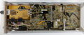
7A14, left side
-
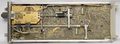
7A14, right side
-
-
-


Measurement examples
Current through a 50 Ω resistor measured with P6021 (top trace) compared to the voltage across the resistor (bottom trace). Measured with 7854 and 7A26 illustrating the low frequency limitation of the different probe termination methods. In the 10 mA/mV setting of the termination box the gain of the scope's vertical amplifier is insufficient to scale the current trace to the same nominal size as the voltage trace.
The signal shown is a squarewave from a PG501 @ 4 Vp-p into 50 Ω = 80 mAp-p.


