7B85: Difference between revisions
(spec) |
No edit summary |
||
| (33 intermediate revisions by 3 users not shown) | |||
| Line 1: | Line 1: | ||
{{Plugin Sidebar | {{Plugin Sidebar | ||
|manufacturer=Tektronix | |||
summary=400 MHz | |series=7000-series scopes | ||
image=Tek 7b85 front.jpg | | |type=7B85 | ||
caption=Tektronix 7B85 Delaying Timebase plug-in| | |summary=400 MHz delaying timebase | ||
introduced=1976 | | |image=Tek 7b85 front.jpg | ||
|caption=Tektronix 7B85 Delaying Timebase plug-in | |||
|introduced=1976 | |||
|discontinued=1990 | |||
* [ | |designers=Les Larson;Bruce Hofer;Paul Farley;Art Metz; | ||
|manuals= | |||
* [[Media:070-1960-00.pdf|7B85 Operator's Manual]] (OCR) | |||
* [[Media:070-1961-00.pdf|7B85 Instruction Manual 070-1961-00]] | |||
* [[Media:070-1961-01.pdf|7B85 Instruction Manual 070-1961-01]] (OCR) | |||
<small> | |||
* [https://bama.edebris.com/download/tek/7b85/Tektronix-7B85%20Delaying%20Time%20Base.pdf 070-1961-01 Alternate copy @ BAMA] | |||
</small> | |||
}} | }} | ||
The '''Tektronix 7B85''' is a 400 MHz delaying timebase for [[7000-series scopes]] with digital delay and delta time read-out capability, typically used in the 7800 Series, e.g. [[7844]]. It does not support X-Y mode. | |||
The | The delay function differentiates the 7B85 from the otherwise similar [[7B80]]. The [[7B87]] is also similar to the 7B85 but provides an acquisition clock for a digital storage mainframe instead of a delay. | ||
an acquisition clock for a digital storage mainframe instead of a delay. | |||
The [[7B85]]/[[7B80]] combination was introduced in 1976 to replace the 200 MHz [[7B71]]/[[7B70]] that had no digital delay read-out. For the [[7104]] 1 GHz-class scopes, the [[7B15]]/[[7B10]] provide the functionality of 7B85/7B80. | |||
From Tekscope Vol.8 No.1, 1976: | |||
<blockquote> | |||
[[Les Larson]] developed the trigger circuitry and served as Project Manager for the 7B80 and 7B85. | |||
The sweeps were designed by [[Bruce Hofer]] and the DVM and related logic by [[Paul Farley]]. Much credit is due [[Art Metz]] for his work on the trigger input IC which includes the peak-to-peak automatic trigger circuitry. | |||
[[Gene Andrews]], Program Manager, provided overall direction for the project. | |||
</blockquote> | |||
{{BeginSpecs}} | {{BeginSpecs}} | ||
{{Spec | Sweep | 5 s/ | {{Spec | Sweep | 5 s/div to 10 ns/iv in 1−2−5 sequence, ×10 magnifier down to 1 ns/div, variable to ×2.5}} | ||
{{Spec |Triggering | to 400 MHz }} | {{Spec |Triggering | to 400 MHz }} | ||
{{Spec | Features | | {{Spec | Features | | ||
* Digital read-out of delay and delta times | |||
* Variable Trigger Holdoff | * Variable Trigger Holdoff | ||
* Peak-to-peak Auto Triggering | * Peak-to-peak Auto Triggering | ||
}} | }} | ||
{{EndSpecs}} | {{EndSpecs}} | ||
==Links== | |||
* [[Patent US 4109182A]], ''Delayed sweep system for an oscilloscope''. | |||
* [https://m.youtube.com/watch?v=Hz-gF_XSj9w Demonstration of delay and delta time measurement on a 7B85] | |||
{{Documents|Link=7B85}} | |||
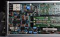
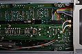
==Internals== | ==Internals== | ||
The 7B85 uses a [[155-0185-00]] digital voltmeter IC (U686). | The 7B85 uses a [[155-0185-00]] digital voltmeter IC (U686). | ||
A ramp generator is started when the trigger signal arrives. | A ramp generator is started when the trigger signal arrives. | ||
The delayed sweep is started when a comparator detects that the ramp has reached a control voltage, set by the front panel knobs on the 7B85. | The delayed sweep is started when a comparator detects that the ramp has reached a control voltage, set by the front panel knobs on the 7B85. | ||
The control voltage is proportional to the amount of delay. | The control voltage is proportional to the amount of delay. | ||
The digital voltmeter in the 7B85 digitizes the control voltage and displays it on the oscilloscope readout, thereby providing | The digital voltmeter in the 7B85 digitizes the control voltage and displays it on the [[7000 series readout system|oscilloscope readout]], thereby providing the operator with a precise readout of the delay. | ||
the operator with a precise readout of the delay. | |||
Another way of setting up a precisely delayed timebase is to use a [[7D11]] digital delay module. | |||
The 7B85 uses the +50 V supply provided by the mainframe. | |||
==Prices== | |||
{| class="wikitable" | |||
|- | |||
! Year | |||
! 1977 | |||
! 1980 | |||
! 1984 | |||
! 1987 | |||
! 1990 | |||
|- | |||
! Catalog price | |||
|align=right| $895 | |||
|align=right| $1,200 | |||
|align=right| $1,700 | |||
|align=right| $1,940 | |||
|align=right| $2,400 | |||
|- | |||
! In 2023 Dollars | |||
|align=right| $4,500 | |||
|align=right| $4,500 | |||
|align=right| $5,000 | |||
|align=right| $5,200 | |||
|align=right| $5,600 | |||
|- | |||
|} | |||
==Pictures== | ==Pictures== | ||
===Hardware=== | |||
<gallery> | <gallery> | ||
Tek 7b85 front.jpg | Front | |||
7b85-left.jpg | 7B85, left side | |||
7b85-left-del-removed.jpg | 7B85, left side, delay board removed | |||
7b85-right.jpg | 7B85, right side | |||
Tek-7b15-vs-7b85-left.jpg | Family resemblance: 7B15 (top) vs. 7B85 (bottom). Left side. | |||
Tek-7b15-vs-7b85-right.jpg | Family resemblance: 7B15 (top) vs. 7B85 (bottom). Right side. | |||
7b85 left rear.jpg | Left rear | |||
7b85 left front.jpg | Left front | |||
7b85 right front.jpg | Right front | |||
7b85 right rear.jpg | Right rear | |||
</gallery> | </gallery> | ||
===Measurements=== | |||
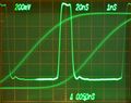
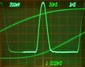
These are examples of measurements with a [[7B85]] in the Horizontal A and a [[7B80]] in the Horizontal B compartment (of a [[7904]]). | |||
Horizontal mode is set to alternating to show the pulse signal being triggered (A) and the delayed/magnified part (B). | |||
<gallery> | |||
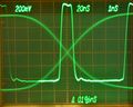
7b85-risetime-5n.jpg | Measuring rise time of a pulse. Delayed signal is scaled for 0-100% on graticule. Delay time is adjusted so the trace crosses the 10% level on the center line. Delta time is adjusted so the delta-delayed trace crosses 90% on the same vertical line. Delta time readout indicates rise time directly. | |||
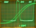
7b85-risetime-10n.jpg | Measuring rise time of a pulse. Same as before, rise time increased to 10 ns (HP8112A generator). | |||
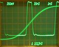
7b85-pulse-width.jpg | Pulse width measurement. Delayed signal and delta-delayed trace cross at 50%. Delta time readout indicates pulse width directly. | |||
7b85-period-1.jpg | Pulse period measurement. Delta time is adjusted to overlay the delayed trace with one delayed by an additional period. In this picture, the two traces do not yet overlay exactly. | |||
7b85-period-2.jpg | Pulse period measurement. Delayed trace overlays with one delayed by an additional period, delta time reads pulse period. | |||
</gallery> | |||
==Components== | |||
{{Parts|7B85}} | |||
[[Category:7000 series horizontal plugins]] | [[Category:7000 series horizontal plugins]] | ||
Latest revision as of 14:13, 4 March 2024

The Tektronix 7B85 is a 400 MHz delaying timebase for 7000-series scopes with digital delay and delta time read-out capability, typically used in the 7800 Series, e.g. 7844. It does not support X-Y mode.
The delay function differentiates the 7B85 from the otherwise similar 7B80. The 7B87 is also similar to the 7B85 but provides an acquisition clock for a digital storage mainframe instead of a delay.
The 7B85/7B80 combination was introduced in 1976 to replace the 200 MHz 7B71/7B70 that had no digital delay read-out. For the 7104 1 GHz-class scopes, the 7B15/7B10 provide the functionality of 7B85/7B80.
From Tekscope Vol.8 No.1, 1976:
Les Larson developed the trigger circuitry and served as Project Manager for the 7B80 and 7B85. The sweeps were designed by Bruce Hofer and the DVM and related logic by Paul Farley. Much credit is due Art Metz for his work on the trigger input IC which includes the peak-to-peak automatic trigger circuitry. Gene Andrews, Program Manager, provided overall direction for the project.
Key Specifications
| Sweep | 5 s/div to 10 ns/iv in 1−2−5 sequence, ×10 magnifier down to 1 ns/div, variable to ×2.5 |
|---|---|
| Triggering | to 400 MHz |
| Features |
|
Links
- Patent US 4109182A, Delayed sweep system for an oscilloscope.
- Demonstration of delay and delta time measurement on a 7B85
Documents Referencing 7B85
| Document | Class | Title | Authors | Year | Links |
|---|---|---|---|---|---|
| Tekscope 1976 V8 N1.pdf | Article | Delta Time Measurement for the 7000 Series | Paul Farley • Les Larson • Bruce Hofer | 1976 | 7B85 • 7B80 • DM40 • DM43 |
| Technology report oct 1979.pdf | Article | Patent Received: 4,109,182 Simultaneous Delayed Sweep Display | Oliver Dalton | 1979 | Patent US 4109182A • 7B80 • 7B85 • 7B10 • 7B15 |
Internals
The 7B85 uses a 155-0185-00 digital voltmeter IC (U686). A ramp generator is started when the trigger signal arrives. The delayed sweep is started when a comparator detects that the ramp has reached a control voltage, set by the front panel knobs on the 7B85. The control voltage is proportional to the amount of delay.
The digital voltmeter in the 7B85 digitizes the control voltage and displays it on the oscilloscope readout, thereby providing the operator with a precise readout of the delay.
Another way of setting up a precisely delayed timebase is to use a 7D11 digital delay module.
The 7B85 uses the +50 V supply provided by the mainframe.
Prices
| Year | 1977 | 1980 | 1984 | 1987 | 1990 |
|---|---|---|---|---|---|
| Catalog price | $895 | $1,200 | $1,700 | $1,940 | $2,400 |
| In 2023 Dollars | $4,500 | $4,500 | $5,000 | $5,200 | $5,600 |
Pictures
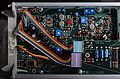
Hardware
-
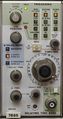
Front
-

7B85, left side
-
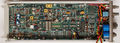
7B85, left side, delay board removed
-

7B85, right side
-

Family resemblance: 7B15 (top) vs. 7B85 (bottom). Left side.
-
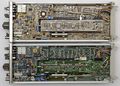
Family resemblance: 7B15 (top) vs. 7B85 (bottom). Right side.
-
Left rear
-

Left front
-
Right front
-
Right rear


Measurements
These are examples of measurements with a 7B85 in the Horizontal A and a 7B80 in the Horizontal B compartment (of a 7904).
Horizontal mode is set to alternating to show the pulse signal being triggered (A) and the delayed/magnified part (B).
-
Measuring rise time of a pulse. Delayed signal is scaled for 0-100% on graticule. Delay time is adjusted so the trace crosses the 10% level on the center line. Delta time is adjusted so the delta-delayed trace crosses 90% on the same vertical line. Delta time readout indicates rise time directly.
-
Measuring rise time of a pulse. Same as before, rise time increased to 10 ns (HP8112A generator).
-
Pulse width measurement. Delayed signal and delta-delayed trace cross at 50%. Delta time readout indicates pulse width directly.
-
Pulse period measurement. Delta time is adjusted to overlay the delayed trace with one delayed by an additional period. In this picture, the two traces do not yet overlay exactly.
-
Pulse period measurement. Delayed trace overlays with one delayed by an additional period, delta time reads pulse period.


Components
Some Parts Used in the 7B85
| Part | Part Number(s) | Class | Description | Used in |
|---|---|---|---|---|
| 155-0049-00 | 155-0049-00 • 155-0049-01 • 155-0049-02 | Monolithic integrated circuit | sweep control with lockout | 335 • 464 • 465 • 466 • 475 • 475A • 475M • 485 • 5B31 • 5B40 • 5B52 • 5B42 • 5B44 • 7B53A • 7B80 • 7B85 • 7B87 • 7B92A • 7B90P • 7B10 • 7B15 • SC502 • 7B42N • AN/USM-281C • 067-0657-00 |
| 155-0090-00 | 155-0090-00 • 155-0090-01 • 155-0090-02 | Monolithic integrated circuit | four-decade counter, latch and D/A converter | 7B85 • 7D01 • 7D12 • 7D15 • 7J20 |
| 155-0109-00 | 155-0109-00 • 155-0109-01 | Monolithic integrated circuit | trigger | 5B25N • 5B31 • 5B40 • 5B42 • 5B44 • 5S14N • 7B50A • 7B53A • 7B80 • 7B85 • 7B87 • 7B81P • 7B90P • 7S14 • 7612D • SC502 • SC503 • SC504 |
| 155-0126-00 | 155-0126-00 | Monolithic integrated circuit | trigger source selector and P-P auto amplifier | 7B50A • 7B80 • 7B85 • 7B87 • 7B81P • 7B90P |
| 155-0171-00 | 155-0171-00 | Monolithic integrated circuit | four-decade counter, latch and D/A converter | 7B85 • 7D01 • 7D12 • 7D15 • 7J20 |
| 155-0185-00 | 155-0185-00 | Monolithic integrated circuit | four-digit Counter, latch and D/A converter/DVM | 7B15 • 7B85 • 7B87 |