O: Difference between revisions
(slight wording revision, added details, fixed formatting) |
No edit summary |
||
| Line 11: | Line 11: | ||
|manuals= | |manuals= | ||
* [[Media:070-323.pdf|Tektronix Type O Manual]] | * [[Media:070-323.pdf|Tektronix Type O Manual]] | ||
* [[Media:Tek type o preliminary | * [[Media:Tek type o preliminary.pdf|Tektronix Type O Preliminary Manual]] | ||
* [[Media:Tek type o irb.pdf|Tektronix Type O Instrument Reference Book]] (OCR) | * [[Media:Tek type o irb.pdf|Tektronix Type O Instrument Reference Book]] (OCR) | ||
Revision as of 06:32, 10 March 2024
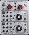
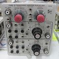
The Tektronix Type O is a letter-series plug-in, designed by Hiro Moriyasu, that contains two operational amplifiers and a vertical amplifier.
It was introduced in mid-1962 and was available through 1973.
The input and feedback networks of the operational amplifiers can be configured from the front panel switches and/or by way of user-supplied components plugged into the front panel banana jacks. Tektronix made several pre-configured plug-in modules to plug directly into those jacks. See the Accessories section below. Note that one of the accessories is an empty box with mating banana plugs for a user-designed circuit.
A mode switch selects the display to be taken from either op-amp's output, or the vertical amplifier input.
Key Specifications
| Bandwidth | DC to 25 MHz (Vertical amplifier1) |
|---|---|
| Rise time | 14 ns (Vertical amplifier 1) |
| Deflection | 50 mV/div to 10 V/div, 1–2–5, and variable (Vertical amplifier) |
| Input | 1 MΩ // 47 pF (Vertical amplifier) |
| Op-Amp GBW | 15 MHz |
| Op-Amp gain | 2500 |
| Op-Amp output | ±50 V, ±5 mA; output impedance 30 Ω @ 1 MHz |
| Op-Amp noise | typ. 0.5 mVp-p referred to the input |
| Internal Z | input and feedback can be selected from 10 kΩ, 100 kΩ, 200 kΩ, 500 kΩ, 1 MΩ or 10 pF to 1 μF in decade steps |
Note 1: In 540- and 580-series scopes and 555
Accessories
- 013-0049-01 Standard Shielded Cover (two supplied with each plugin)
- 013-0048-01 Terminal Adapter Assembly (empty box for user chosen components)
- 013-0081-00 Compensating Adapter
- 013-0068-00 Gating Adapter
- 013-0086-00 Leakage Current Adapter
- 013-0067-00 Logarithmic Amplifier Adapter
- 067-0507-00 Grid Current Checker (calibration fixture)
Prices
- $625 in 1971 ($4,700 in 2023 dollars)
Internals
The opamps are implemented using two 12AU6 as a differential pair followed by two systems of a 6DJ8 as a bootstrapped cathode follower.
The vertical amplifier also starts with a 12AU6 differential pair, which is followed by a pair of 2N1143 200 MHz transistors.
Pictures
-
Front view
-
Front view
-
Top view
-
Right view
-
Left view
-
-
-
-
-
-
-
-
-
-
pre-production Type O
Schematics
-
Opamp Schematic
-
Preamp Schematic
Components
Some Parts Used in the O
| Part | Part Number(s) | Class | Description | Used in |
|---|---|---|---|---|
| 12AU6 | 154-0040-00 | Vacuum Tube (Pentode) | RF pentode | 81 • 112 • 1L10 • 1L20 • 1L60 • 3L10 • 512 • 556 • 575 • 545 • 547 • 549 • 581 • 585 • A • B • C • G • K • H • L • ML • M • N • O • R • S • Z |
| 6DJ8 | 154-0187-00 • 154-0305-00 | Vacuum Tube (Dual Triode) | dual triode | 067-506 • 111 • 132 • 161 • 310A • 316 • 317 • 502 • 502A • 503 • 504 • 506 • 515 • 516 • 519 • 526 • 529 • RM529 • 533 • 535 • 536 • 543 • 544 • 545 • 545A • 545B • 546 • 547 • 549 • 555 • 556 • 561A • 561S • 564 • 565 • 567 • 581 • 581A • 585 • 585A • 661 • 1A4 • 1S1 • 60 • 2A60 • 63 • 2A63 • 67 • 2B67 • 3A1 • 3A1S • 3A2 • 3A3 • 3A6 • 3A7 • 72 • 3A72 • 75 • 3A75 • 4S2 • 51 • 3B1 • 3B1S • 3B2 • 3B3 • 3B4 • 3M1 • 3S76 • 3T77 • 3T77A • 9A1 • 9A2 • 1121 • 80 • 81 • 82 • 86 • B • O • W • Z • Telequipment D56 • Telequipment S32A • Telequipment D52 • S-311 • Telequipment TD51 • Telequipment S52 • Telequipment S51 • Telequipment Type A • TU-4 |
| 8426 | Vacuum Tube (Pentode) | RF pentode | O • 545A • 547 • 549 • 581A • 585A |


