DC509: Difference between revisions
Jump to navigation
Jump to search
No edit summary |
|||
| (12 intermediate revisions by 3 users not shown) | |||
| Line 1: | Line 1: | ||
{{TM500 | | {{TM500 | ||
mfg=Tektronix | | |mfg=Tektronix | ||
type=DC509 | | |class=counter | ||
function=135 MHz programmable frequency counter | |type=DC509 | ||
|function=135 MHz programmable frequency counter | |||
image=dc509-front.jpg | | |image=dc509-front.jpg | ||
introduced=1981 | | |introduced=1981 | ||
discontinued=(?) | | |discontinued=(?) | ||
manuals= | ||manuals= | ||
* [ | * [[Media:070-3464-00.pdf|Tektronix DC509 Manual]] | ||
<small> | <small> | ||
'''Modifications''' | '''Modifications''' | ||
| Line 16: | Line 16: | ||
It is internally similar to the [[DC5009]] to which it could be converted through an upgrade kit. | It is internally similar to the [[DC5009]] to which it could be converted through an upgrade kit. | ||
{{ | The DC509 uses reciprocal counting with an internal 100 MHz clock phase-locked to the reference oscillator. | ||
An R6504 microprocessor (28-pin variant of a [[MOS Technology 6502|6502]] with 8K addressable memory) performs the calculations. | |||
Opt.01 is an [[wikipedia:Crystal oven|OCXO]] for improved stability. | |||
{{BeginSpecs}} | |||
{{Spec|Resolution | 8 digits}} | |||
{{Spec | Frequency | ≤100 μHz to ≥135 MHz (Ch B in Ratio: ≥125 MHz) }} | |||
{{Spec | Time A-B | ≤15 ns to ≥3.05 hours }} | |||
{{Spec | Single shot resolution | 10 ns }} | |||
{{Spec | Totalize | 2<sup>40</sup> counts (1.09 × 10<sup>12</sup>) }} | |||
{{SpecGroup | Standard time base }} | |||
{{Spec | Frequency | 10 MHz ± 1 × 10<sup>-7</sup> at cal }} | |||
{{Spec | Error | ≤ ±5 × 10<sup>-6</sup> from 0 °C to +50 °C }} | |||
{{Spec | Aging | ≤ ±1 × 10<sup>-6</sup> per year }} | |||
{{SpecGroup | Opt.01 OCXO time base }} | |||
{{Spec | Frequency | 10 MHz ± 2 × 10<sup>-8</sup> at cal }} | |||
{{Spec | Error | ≤ ±2 × 10<sup>-7</sup> from 0 °C to +50 °C (after oven warm-up) }} | |||
{{Spec | Aging | ≤ ±1 × 10<sup>-8</sup> per day }} | |||
{{EndSpecs}} | |||
==Links== | ==Links== | ||
{{Documents|Link=DC509}} | |||
{{PatentLinks|DC509}} | |||
==Rear interface== | |||
<small> | |||
{| | |||
|- | |||
|28B − Gate Out (TTL, active high) || 27B − Arming in GND | |||
|- | |||
|27B || 27A − Arming in (TTL, active high) | |||
|- | |||
|26B − Remote Start || 26A − Reset in (active low) | |||
|- | |||
|25B | |||
|- | |||
|24B − Shaped Out B || Shaped Out B GND | |||
|- | |||
|23B − Shaped Out A GND || Shaped Out A | |||
|- | |||
|22B − Trig Level CH B || 22A − Trig Level CH A | |||
|- | |||
|21B | |||
|- | |||
|20B | |||
|- | |||
|19B | |||
|- | |||
|18B | |||
|- | |||
|17B − CH B input (50 Ω, ≤10 V<sub>RMS</sub>) || 17A − CH A input GND | |||
|- | |||
|16B − CH B input GND || 16A − CH A input (50 Ω, ≤10 V<sub>RMS</sub>) | |||
|- | |||
|15B − 10 MHz clock out || 15A − 10 MHz clock out GND | |||
|- | |||
|14B − Prescale; when low, counter divides readout by 16 || 14A − External clock Input | |||
|- | |||
|} | |||
</small> | |||
==Firmware (uploaded BIN files)== | ==Firmware (uploaded BIN files)== | ||
| Line 27: | Line 82: | ||
* [[Media:160-1092-02.bin|160-1092-02.bin]] U1201 DC5009 | * [[Media:160-1092-02.bin|160-1092-02.bin]] U1201 DC5009 | ||
==Pictures== | |||
<gallery> | |||
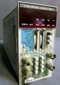
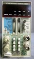
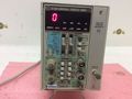
Tek DC509 front.JPG |(Labels GHz, MHz, kHz, Hz have been reprinted) | |||
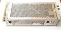
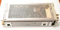
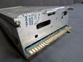
Tek DC509 left.JPG | |||
Tek DC509 right.jpg | |||
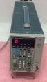
Tek dc509 1.jpg | |||
Tek dc509 2.jpg | |||
Tek dc509 3.jpg | |||
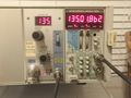
Tek dc509 4.jpg | |||
Tek dc509 5.jpg | |||
Tek dc509 6.jpg | |||
Tek dc509 7.jpg | |||
Tek dc509 8.jpg | |||
Tek dc509 9.jpg | |||
Tek dc509 10.jpg | |||
</gallery> | |||
{{ | ==Components== | ||
{{Parts|DC509}} | |||
Latest revision as of 05:17, 6 October 2024

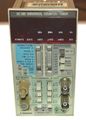
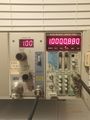
The Tektronix DC509 is a 135 MHz programmable frequency counter plug-in for the TM500 system.
It is internally similar to the DC5009 to which it could be converted through an upgrade kit.
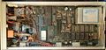
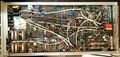
The DC509 uses reciprocal counting with an internal 100 MHz clock phase-locked to the reference oscillator. An R6504 microprocessor (28-pin variant of a 6502 with 8K addressable memory) performs the calculations.
Opt.01 is an OCXO for improved stability.
Key Specifications
| Resolution | 8 digits |
|---|---|
| Frequency | ≤100 μHz to ≥135 MHz (Ch B in Ratio: ≥125 MHz) |
| Time A-B | ≤15 ns to ≥3.05 hours |
| Single shot resolution | 10 ns |
| Totalize | 240 counts (1.09 × 10¹²) |
| — Standard time base — | |
| Frequency | 10 MHz ± 1 × 10⁻⁷ at cal |
| Error | ≤ ±5 × 10⁻⁶ from 0 °C to +50 °C |
| Aging | ≤ ±1 × 10⁻⁶ per year |
| — Opt.01 OCXO time base — | |
| Frequency | 10 MHz ± 2 × 10⁻⁸ at cal |
| Error | ≤ ±2 × 10⁻⁷ from 0 °C to +50 °C (after oven warm-up) |
| Aging | ≤ ±1 × 10⁻⁸ per day |
Links
Documents Referencing DC509
| Document | Class | Title | Authors | Year | Links |
|---|---|---|---|---|---|
| Tekscope 1981 V13 N1.pdf | Article | New Products | 1981 | PG507 • DC509 | |
| 070-2088-04.pdf | Book | TM500 Series Rear Interface Data Book | 1985 | AA501 • AF501 • AM501 • AM502 • AM503 • AM511 • DC501 • DC502 • DC503 • DC503A • DC504 • DC505 • DC505A • DC508 • DC508A • DC509 • DC510 • DC5009 • DC5010 • DD501 • DL502 • DM501 • DM501A • DM502 • DM502A • DM505 • DM5010 • FG501 • FG501A • FG502 • FG503 • FG504 • FG507 • FG5010 • LA501 • LA501W • WR501 • MR501 • PG501 • PG502 • PG505 • PG506 • PG507 • PG508 • PS501 • PS502 • PS503 • PS503A • PS505 • PS5010 • RG501 • SC501 • SC502 • SC503 • SC504 • SG502 • SG503 • SG504 • SG505 • SW503 • TG501 • TR501 • TR502 • MI5010 • MX5010 • SI5010 |
Rear interface
| 28B − Gate Out (TTL, active high) | 27B − Arming in GND |
| 27B | 27A − Arming in (TTL, active high) |
| 26B − Remote Start | 26A − Reset in (active low) |
| 25B | |
| 24B − Shaped Out B | Shaped Out B GND |
| 23B − Shaped Out A GND | Shaped Out A |
| 22B − Trig Level CH B | 22A − Trig Level CH A |
| 21B | |
| 20B | |
| 19B | |
| 18B | |
| 17B − CH B input (50 Ω, ≤10 VRMS) | 17A − CH A input GND |
| 16B − CH B input GND | 16A − CH A input (50 Ω, ≤10 VRMS) |
| 15B − 10 MHz clock out | 15A − 10 MHz clock out GND |
| 14B − Prescale; when low, counter divides readout by 16 | 14A − External clock Input |
Firmware (uploaded BIN files)
- 160-1076-02.bin U1312 DC5009
- 160-1091-02.bin U1102 DC5009
- 160-1092-02.bin U1201 DC5009
Pictures
-
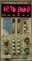
(Labels GHz, MHz, kHz, Hz have been reprinted)
-
-
-
-
-
-
-
-
-
-
-
-


Components
Some Parts Used in the DC509
| Part | Part Number(s) | Class | Description | Used in |
|---|---|---|---|---|
| 148-0128-00 | 148-0128-00 | Discrete component | miniature magnetic latching relay armature | DC509 • DC5009 • SG5030 |
| 2N4249 | 151-0342-00 | Discrete component | PNP Si low noise amp. | DC501 • DC502 • DC503 • DC503A • DC504 • DC504A • DC505 • DC505A • DC508 • DC508A • DC509 • DC510 |
| Rockwell R6504 | 156-1482-00 | Monolithic integrated circuit | 8-bit microprocessor | DC509 • DC5009 |
| Rockwell R6531 | 156-1530-00 | Monolithic integrated circuit | ROM-RAM-I/O-Counter (RRIOC) | DC509 |