DC505: Difference between revisions
Jump to navigation
Jump to search
No edit summary |
No edit summary |
||
| Line 16: | Line 16: | ||
}} | }} | ||
{{EndSpecs}} | {{EndSpecs}} | ||
==Links== | |||
* [http://www.barrytech.com/tektronix/tektm500/tekdc505.html DC505 @ barrytech.com] | |||
{{Documents|Link=DC505}} | |||
==Rear Interface== | ==Rear Interface== | ||
{| class="wikitable" | {| class="wikitable" | ||
| Line 46: | Line 51: | ||
| 14A || Ext Clock Input | | 14A || Ext Clock Input | ||
|} | |} | ||
Data is output serially by digit | Data is output serially by digit. | ||
==Pictures== | ==Pictures== | ||
Revision as of 09:53, 12 October 2023

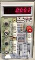
The Tektronix DC505 is a 225 MHz counter/timer plug-in for the TM500 system.
Key Specifications
| Frequency range | 0 Hz (DC coupled) / 10 Hz (AC coupled) to 225 MHz |
|---|---|
| Sensitivity | 50 mVRMS to 150 MHz, 100 mVRMS to 225 MHz (sine) |
| Resolution | 7 digits |
| Gate time | 0.01 s to 10 s in decade steps |
| Stability | Standard: 1×10⁻⁵; Opt.1: 5×10⁻⁷ (0°C to +50°C, after 30 min warm-up) |
| Long-term drift | Standard: 1×10⁻⁵ per month; Opt.1: 5×10⁻⁷ per month |
| Features |
|
Links
Documents Referencing DC505
Rear Interface
| Connector Pin | Signal |
|---|---|
| 27A | Internal Scan Clock Disable |
| 26B | Manual Start-Stop |
| 26A | /RESET |
| 25B,24B | Internal Scan Clock Out |
| 25A | Time Slot Zero |
| 23B | Overflow |
| 21B | BCD output 2 |
| 20B | BCD output 8 |
| 20A | BCD output 4 |
| 19A | BCD output 1 |
| 19B | Data Good |
| 14A | Ext Clock Input |
Data is output serially by digit.
Pictures
-
DC505
-

DC505A
