507: Difference between revisions
No edit summary |
No edit summary |
||
| (27 intermediate revisions by 4 users not shown) | |||
| Line 1: | Line 1: | ||
The Tektronix Type 507 was designed for the power industry for surge testing. | {{Oscilloscope Sidebar | ||
It was [[introduced in 1959]]. | |manufacturer=Tektronix | ||
|series= | |||
of | |model=507 | ||
|summary=Power Industry scope | |||
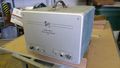
|image=Tek 507 front3.jpg | |||
|caption=507 | |||
|introduced=1959 | |||
|discontinued=1974 | |||
|designers=Chuck Nolan; | |||
|manuals= | |||
* [[Media:IM-507-1.pdf|Tektronix 507 Manual IM-507-1]] (OCR) | |||
* [[Media:070-372.pdf|Tektronix 507 Manual 070-372]] needed | |||
'''Articles''' | |||
* [https://w140.com/w_d_bunting_reliable_spark_gap_for_capacitor_bank_switching.pdf W. D. Bunting, "A Reliable Spark Gap For Capacitor Bank Switching" (OCR)] | |||
* [https://w140.com/thomas_and_hearst-measurement_of_exploding_wire_energy.pdf Thomas and Hearst, "An Electronic Scheme for Measurement of Exploding Wire Energy" (OCR)] | |||
}} | |||
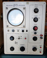
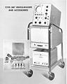
The '''Tektronix Type 507''' was designed for the power industry for surge testing. | |||
It was [[introduced in 1959]]. Development of the 507 was led by [[Chuck Nolan]]. | |||
The | The scope was intended to operate in an environment of strong electromagnetic fields. | ||
It does not take plug-ins. The power supply is external, like in the [[517]], [[551]], and [[555]]. | |||
The 507 has | The vertical signal path of the 507 does not contain amplifiers. It has a 5 nanosecond risetime. | ||
power supplies, located in the external box, are all tube except for [[selenium rectifiers]] for some | The input impedance of the 507 is 72 Ω. The maximum sensitivity is deliberately low, at 50 V/cm. | ||
of the lower voltages. | |||
The input attenuator is very unusual for Tek scopes. It is a switch with ten positions in "% of signal", where each step is 10%. | |||
The deflection signal is permanently AC-coupled and, unusually, the DC blocking capacitor is after the input attenuator. | |||
The 507 has a total acceleration voltage of 24 kV, produced by four [[1X2]] tubes. | |||
The lower-voltage power supplies, located in the external box, are all tube except for [[selenium rectifiers]] for some of the lower voltages. | |||
The 507 uses the [[T507]] CRT. | |||
==Links== | |||
* [[Media:Service Scope 18 Feb 1963.pdf | Service Scope No. 18, Feb 1963]]: Anode-Connector Arcing in the Type 507 Oscilloscope | |||
==Pictures== | |||
<gallery> | <gallery> | ||
Tek 507 front.jpg|507 | |||
507_w_cart.JPG | 507 with [[202]] cart | |||
Tek 507 front2.jpg|507 | |||
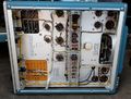
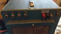
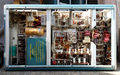
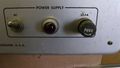
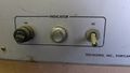
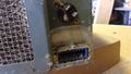
Tek 507 power supply front.jpg|507 power supply | |||
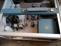
Tek 507 ps bottom1.jpg|507 power supply bottom | |||
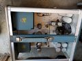
Tek 507 ps3.jpg|507 power supply | |||
Tek 507 ps4.jpg|507 power supply | |||
Tek 507 ps6.jpg|507 power supply | |||
Tek 507 rear1.jpg|507 rear | |||
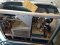
Tek 507 right internal1.jpg|507 right internal | |||
Tek 507 right internal2.jpg|507 right internal | |||
Tek 507 right top.jpg|507 top | |||
Tek 507 bottom.jpg|507 bottom | |||
Tek 507.jpg|507 on Cart | |||
Tek 507 and ps.jpg|507 with Power Supply | |||
Tek 507 at general electric.jpg|507 at General Electric | |||
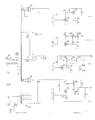
Tek 507 block diagram.png|Block Diagram | |||
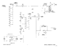
Tek 507 sweep trigger and trip pulse.png|Sweep Trigger and Trip Pulse | |||
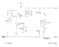
Tek 507 time mark generator.png|Time Mark Generator | |||
Tek 507 vertical deflection.png|Vertical Deflection | |||
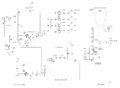
Tek 507 horizontal amp.png|Horizontal Amplifier | |||
Tek 507 crt circuit.png|CRT Circuit | |||
Tek_507_heater_wiring.png|Heater Wiring | |||
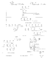
Tek 507 power supply.png|Power Supply | |||
Tek 507 ps 1.jpg | |||
Tek 507 ps 2.jpg | |||
Tek 507 ps 3.jpg | |||
Tek 507 ps 4.jpg | |||
Tek 507 ps 5.jpg | |||
Tek 507 ps 6.jpg | |||
Tek 507 ps 7.jpg | |||
Tek 507 ps 8.jpg | |||
Tek 507 ps 9.jpg | |||
Tek 507 ps 10.jpg | |||
Tek 507 ps 11.jpg | |||
Tek 507 ps 12.jpg | |||
Tek 507 and ps.jpg | |||
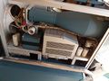
Tek 507 attenuator 1.jpg|Input Attenuator. The two unconnected wires at the right side are the CRT vertical deflection plate connection. | |||
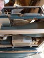
Tek 507 attenuator 2.jpg|Input Attenuator. The thicker coax with the copper braid is the input signal. The thinner coax with the steel braid comes from the internal time mark generator. | |||
</gallery> | </gallery> | ||
{{Parts|507}} | |||
[[Category:Monolithic tube scopes]] | |||
Latest revision as of 05:27, 2 November 2022

The Tektronix Type 507 was designed for the power industry for surge testing. It was introduced in 1959. Development of the 507 was led by Chuck Nolan.
The scope was intended to operate in an environment of strong electromagnetic fields. It does not take plug-ins. The power supply is external, like in the 517, 551, and 555.
The vertical signal path of the 507 does not contain amplifiers. It has a 5 nanosecond risetime. The input impedance of the 507 is 72 Ω. The maximum sensitivity is deliberately low, at 50 V/cm.
The input attenuator is very unusual for Tek scopes. It is a switch with ten positions in "% of signal", where each step is 10%. The deflection signal is permanently AC-coupled and, unusually, the DC blocking capacitor is after the input attenuator.
The 507 has a total acceleration voltage of 24 kV, produced by four 1X2 tubes. The lower-voltage power supplies, located in the external box, are all tube except for selenium rectifiers for some of the lower voltages.
The 507 uses the T507 CRT.
Links
- Service Scope No. 18, Feb 1963: Anode-Connector Arcing in the Type 507 Oscilloscope
Pictures
-
507
-
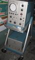
507 with 202 cart
-
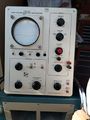
507
-
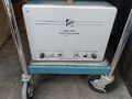
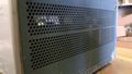
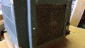
507 power supply
-
507 power supply bottom
-
507 power supply
-

507 power supply
-
507 power supply
-
507 rear
-
507 right internal
-
507 right internal
-
507 top
-
507 bottom
-
507 on Cart
-

507 with Power Supply
-
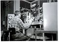
507 at General Electric
-

Block Diagram
-
Sweep Trigger and Trip Pulse
-
Time Mark Generator
-
Vertical Deflection
-
Horizontal Amplifier
-
CRT Circuit
-
Heater Wiring
-
Power Supply
-
-
-
-
-
-

-
-
-
-
-
-
-
-
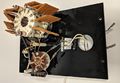
Input Attenuator. The two unconnected wires at the right side are the CRT vertical deflection plate connection.
-
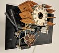
Input Attenuator. The thicker coax with the copper braid is the input signal. The thinner coax with the steel braid comes from the internal time mark generator.


Some Parts Used in the 507
| Part | Part Number(s) | Class | Description | Used in |
|---|---|---|---|---|
| 12AU7 | 154-041 • 154-0041-00 • 154-0287-00 | Vacuum Tube (Dual Triode) | dual medium-μ triode | 104 • 104A • 122 • 160 • 161 • 162 • 181 • 190 • 310 • 310A • 316 • 317 • 3C66 • 502 • 502A • 507 • 511A • 512 • 516 • 517 • 517A • 524 • 526 • 535 • 536 • 545 • 545A • 545B • 547 • 549 • 555 • 561 • 564 • 570 • 575 • 581 • 581A • 585 • 585A • C • D • E • N • Q • Hickok 1825 |
| 1X2 | 154-0005-00 | Vacuum Tube (Diode) | high-voltage rectifier | 420 • 507 • 565 |
| 6AQ5 | 154-017 • 154-0017-00 | Vacuum Tube (Pentode) | beam pentode | 310 • 310A • 316 • 360 • 507 • 511A • 512 • 517 • 517A • 524 • 536 • 570 • 575 |
| 6AU5 | 154-021 • 154-0021-00 | Vacuum Tube (Pentode) | 10 W beam power pentode | 507 • 513 • 516 • 517 • 517A • 531 • 535 • 541 • 535 • 545 • 547 • 581 • 581A • 585 • 585A |
| 6C4 | 154-029 • 154-0029-00 | Vacuum Tube (Triode) | VHF triode | 190 • 3B2 • 507 • 511 • 511A • 517 • 517A • Chemtrix 205 |
| T507 | CRT | 507 |