7A42: Difference between revisions
No edit summary |
No edit summary |
||
| (12 intermediate revisions by the same user not shown) | |||
| Line 13: | Line 13: | ||
** [[Media:070-4286-00.pdf|070-4286-00 Volume 1]] (OCR) | ** [[Media:070-4286-00.pdf|070-4286-00 Volume 1]] (OCR) | ||
** [[Media:070-4654-00.pdf|070-4654-00 Volume 2, Signature Analysis Tables]] (OCR) | ** [[Media:070-4654-00.pdf|070-4654-00 Volume 2, Signature Analysis Tables]] (OCR) | ||
<small> | <small> | ||
'''ROM images''' | '''ROM images''' | ||
| Line 21: | Line 20: | ||
</small> | </small> | ||
}} | }} | ||
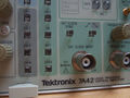
The '''Tektronix 7A42''' is a four-channel 350 MHz plug-in for [[7000-series scopes]]. | The '''Tektronix 7A42''' is a four-channel 350 MHz plug-in for [[7000-series scopes]]. It is a double-wide plug-in, with signal outputs and mainframe readout only using the left slot. | ||
It was specifically designed for logic signals (TTL, ECL, CMOS) and supports triggering based on Boolean conditions of the four inputs. | It was specifically designed for logic signals (TTL, ECL, CMOS) and supports triggering based on Boolean conditions of the four inputs. | ||
A fifth trace, "Trigger View", displays the trigger function output or external clock input. | |||
A | There are two sets of conditions, A and B, that can be individually selected or paired in an "A then B" mode called ''nested triggering'', where the occurrence of condition A arms the trigger and condition B causes the trigger to be generated. | ||
The trigger can be qualified by an external clock. A trigger filter control, variable from 0-300 ns, allows events shorter than the selected length to be suppressed. A TTL-level "reset" input will inhibit the trigger if active. | |||
Selected by an internal jumper, either the trigger signal, or the "A then B" interval, is available on a front-panel trigger output. This can e.g. be routed to a counter for time measurement or event counting. | |||
Tektronix recommended the [[P6131]], | The input V/Div setting can only be seen in the mainframe's readout. | ||
There is a jumper to allow the readout to work in a [[7854]] mainframe. | |||
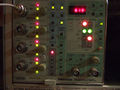
The trigger level is set digitally and shown on a 7-segment display. | |||
Tektronix recommended the [[P6131]], 300 MHz, 10 MΩ ×10 probe, and the [[P6230]], 1.5 GHz, 450/50 Ω ×10, variable-offset probe for ECL circuits. | |||
The [[067-1155-99]] calibration fixture is specific to the 7A42. | The [[067-1155-99]] calibration fixture is specific to the 7A42. | ||
{{BeginSpecs}} | {{BeginSpecs}} | ||
{{Spec | Bandwidth | 350 MHz}} | {{Spec | Bandwidth | 350 MHz }} | ||
{{Spec | Deflection | | {{Spec | Deflection | | ||
* 0.1 / 0.2 / 0.5 V/Div (TTL mode) | * 0.1 / 0.2 / 0.5 V/Div (TTL mode) | ||
* 20 / 50 / 100 mV/Div (ECL mode) | * 20 / 50 / 100 mV/Div (ECL mode) | ||
* each direct or through 10:1 probe}} | * each direct or through 10:1 probe | ||
* always DC coupled }} | |||
{{Spec | Input impedance | 1 MΩ // 15 pF or 50 Ω}} | {{Spec | Input impedance | 1 MΩ // 15 pF or 50 Ω}} | ||
{{Spec | Max. input voltage | | {{Spec | Max. input voltage | | ||
| Line 51: | Line 57: | ||
{{Spec | Weight | 2.8 kg / 6.2 lb}} | {{Spec | Weight | 2.8 kg / 6.2 lb}} | ||
{{EndSpecs}} | {{EndSpecs}} | ||
==Links== | |||
{{Documents|Link=7A42}} | |||
==See also== | |||
* [[067-1155-99]] | |||
* [[A6701]] | |||
* [[821]] | |||
==Internals== | ==Internals== | ||
The 7A42's functions are controlled by an [[Intel 8085]]A microprocessor. | The 7A42's functions are controlled by an [[Intel 8085]]A microprocessor, with code in three 2764 EPROMs (a fourth ROM socket is unused). The front-panel pushbuttons are handled by an Intel 8279 keyboard controller. | ||
Each of the four input attenuator | Each of the four [[119-1517-00]] input attenuator modules contains five [[148-0145-00|148-0145-00 miniature bi-stable relay actuators]]. These have four long pins plugging in to the base board, driving two solenoids that move aa yoke which is held in the last active position by a permanent magnet. The yoke moves a pair of contact springs that directly short corresponding pads on the thick-film ceramic substrate. The relay coils are wired in a 4×5 matrix. | ||
The 7A42 contains its own switch mode PSU, based on an SG3524 controller, that generates +5 V, −2 V and −5 V from the mainframe's ±50 V rails. | The 7A42 contains its own switch mode PSU, based on an SG3524 controller, that generates +5 V, −2 V and −5 V from the mainframe's ±50 V rails. | ||
| Line 61: | Line 75: | ||
There is a [[7A42/Repairs|NiCd backup battery]] that allows the unit to retain its last configuration. | There is a [[7A42/Repairs|NiCd backup battery]] that allows the unit to retain its last configuration. | ||
A 555 timer implements a 15 ms "real-time clock" and watchdog reset, another drives a beeper. | |||
An internal jumper enables partial compatibility with a [[7854]] mainframe in storage mode (displaying any single channel, 1+2 in ALT, or 3+4 in ALT only). There are no restrictions with the 7854 in analog mode. | |||
==Pictures== | ==Pictures== | ||
| Line 80: | Line 93: | ||
Tek 7a42 fr6.jpg | 7A42 rear view | Tek 7a42 fr6.jpg | 7A42 rear view | ||
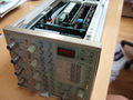
Tek 7a42 fr7.jpg | 7A42 top view | Tek 7a42 fr7.jpg | 7A42 top view | ||
Tek-7A42-Bus.jpg | Schematic cartoon: Bus | |||
Tek-7A42-Chirp.jpg | Schematic cartoon: Chirp | |||
</gallery> | </gallery> | ||
'''Internal''' | '''Internal''' | ||
<gallery> | <gallery> | ||
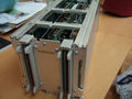
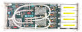
7A42 amplifier board.jpg | amplifier board (one attenuator cover removed) | |||
Tek 7a42 fr11.jpg | amplifier board front - attenuators, amplifiers, channel switches | |||
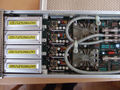
Tek 7a42 fr12.jpg | amplifier board rear - channel switches, two 15 ns delay lines | |||
Tek 7a42 fr11.jpg | amplifier board front - attenuators, amplifiers, channel switches | 7A42 attenuator 1.jpg | attenuator, cover removed | ||
Tek 7a42 fr12.jpg | amplifier board rear - channel switches, two 15 ns delay lines | 7A42 attenuator cover.jpg | attenuator cover | ||
7A42 attenuator 2.jpg | attenuator, top | |||
7A42 attenuator 3.jpg | attenuator, one relay actuator removed | |||
7A42 attenuator 4.jpg | attenuator, all relay actuators removed | |||
7A42 attenuator 5.jpg | attenuator, all relay actuators removed | |||
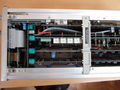
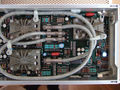
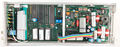
Tek 7a42 fr10.jpg | microprocessor board | |||
Tek 7a42 fr8.jpg | memory backup battery on microprocessor board replaced with LiIon | |||
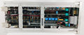
Tek 7a42 fr9.jpg | internal switch mode PSU for digital logic supplies | |||
Tek 7a42 13.jpg | Tek 7a42 13.jpg | ||
Tek 7a42 14.jpg | Tek 7a42 14.jpg | ||
Latest revision as of 02:36, 12 February 2024

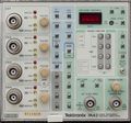
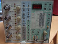
The Tektronix 7A42 is a four-channel 350 MHz plug-in for 7000-series scopes. It is a double-wide plug-in, with signal outputs and mainframe readout only using the left slot.
It was specifically designed for logic signals (TTL, ECL, CMOS) and supports triggering based on Boolean conditions of the four inputs. A fifth trace, "Trigger View", displays the trigger function output or external clock input.
There are two sets of conditions, A and B, that can be individually selected or paired in an "A then B" mode called nested triggering, where the occurrence of condition A arms the trigger and condition B causes the trigger to be generated. The trigger can be qualified by an external clock. A trigger filter control, variable from 0-300 ns, allows events shorter than the selected length to be suppressed. A TTL-level "reset" input will inhibit the trigger if active.
Selected by an internal jumper, either the trigger signal, or the "A then B" interval, is available on a front-panel trigger output. This can e.g. be routed to a counter for time measurement or event counting.
The input V/Div setting can only be seen in the mainframe's readout. There is a jumper to allow the readout to work in a 7854 mainframe. The trigger level is set digitally and shown on a 7-segment display.
Tektronix recommended the P6131, 300 MHz, 10 MΩ ×10 probe, and the P6230, 1.5 GHz, 450/50 Ω ×10, variable-offset probe for ECL circuits.
The 067-1155-99 calibration fixture is specific to the 7A42.
Key Specifications
| Bandwidth | 350 MHz |
|---|---|
| Deflection |
|
| Input impedance | 1 MΩ // 15 pF or 50 Ω |
| Max. input voltage |
|
| Trigger level |
|
| Hysteresis | 40 mV (TTL), 8 mV (ECL) (or ×10) |
| Features |
|
| Weight | 2.8 kg / 6.2 lb |
Links
Documents Referencing 7A42
| Document | Class | Title | Authors | Year | Links |
|---|---|---|---|---|---|
| 42W-5588.pdf | Application Note | Advanced Triggering Techniques | Roger Ensrud | 1984 | 7A42 • 7D11 • 7D15 |
See also
Internals
The 7A42's functions are controlled by an Intel 8085A microprocessor, with code in three 2764 EPROMs (a fourth ROM socket is unused). The front-panel pushbuttons are handled by an Intel 8279 keyboard controller.
Each of the four 119-1517-00 input attenuator modules contains five 148-0145-00 miniature bi-stable relay actuators. These have four long pins plugging in to the base board, driving two solenoids that move aa yoke which is held in the last active position by a permanent magnet. The yoke moves a pair of contact springs that directly short corresponding pads on the thick-film ceramic substrate. The relay coils are wired in a 4×5 matrix.
The 7A42 contains its own switch mode PSU, based on an SG3524 controller, that generates +5 V, −2 V and −5 V from the mainframe's ±50 V rails.
There is a NiCd backup battery that allows the unit to retain its last configuration.
A 555 timer implements a 15 ms "real-time clock" and watchdog reset, another drives a beeper.
An internal jumper enables partial compatibility with a 7854 mainframe in storage mode (displaying any single channel, 1+2 in ALT, or 3+4 in ALT only). There are no restrictions with the 7854 in analog mode.
Pictures
-
-
-

-
-
-
-
-
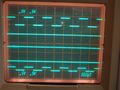
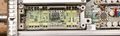
display - four signal traces plus trigger view
-
-
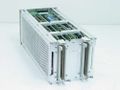
7A42 rear view
-
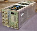
7A42 top view
-
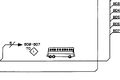
Schematic cartoon: Bus
-
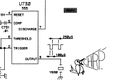
Schematic cartoon: Chirp


Internal
-
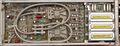
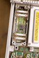
amplifier board (one attenuator cover removed)
-
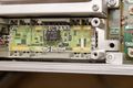
amplifier board front - attenuators, amplifiers, channel switches
-
amplifier board rear - channel switches, two 15 ns delay lines
-
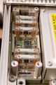
attenuator, cover removed
-
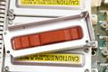
attenuator cover
-
attenuator, top
-
attenuator, one relay actuator removed
-
attenuator, all relay actuators removed
-
attenuator, all relay actuators removed
-
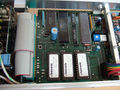
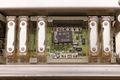
microprocessor board
-
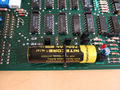
memory backup battery on microprocessor board replaced with LiIon
-
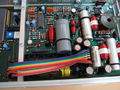
internal switch mode PSU for digital logic supplies
-
-
-


Components
Some Parts Used in the 7A42
| Part | Part Number(s) | Class | Description | Used in |
|---|---|---|---|---|
| 148-0145-00 | 148-0145-00 | Discrete component | miniature bi-stable relay actuator | 7A42 • 119-1517-00 |
| 155-0038-01 | 155-0038-00 • 155-0038-01 | Monolithic integrated circuit | 5-bit current source D/A converter | 7A42 • 7D13 • 7D14 • 7M13 • T4005 |
| 155-0078-00 | 155-0078-xx • 155-0273-00 • 155-0274-00 | Monolithic integrated circuit | broadband amplifier | 464 • 465 • 466 • 468 • 475 • 475A • 475M • 485 • 7834 • 7844 • 7854 • 7904 • R7903 • R7912 • 7912AD • 7912HB • 7104 • 7A16A • 7A16P • 7A24 • 7A26 • 7A42 • 067-0587-01 • 067-0680-00 • AM503 • PG502 • PG508 • DC510 • DC5010 • FG5010 |
| 155-0236-00 | 155-0236-00 | Hybrid integrated circuit | channel switch | 2445 • 2465 • 7A42 |
| ICM7218 | 156-1621-00 • 156-1622-00 | Monolithic integrated circuit | 8-digit, 7-segment LED driver | 7A42 |
| Intel 8085 | 156-1088-00 | Monolithic integrated circuit | 8-bit microprocessor | 308 • 468 • 4025 • 7A42 • 7D02 • AFG5101 • AFG5102 |