647: Difference between revisions
No edit summary |
No edit summary |
||
| (60 intermediate revisions by 7 users not shown) | |||
| Line 1: | Line 1: | ||
{{Oscilloscope Sidebar | |||
|manufacturer=Tektronix | |||
|model=647 | |||
and | |series=647 | ||
|summary=50 MHz scope | |||
|image=647a_1.jpg | |||
|caption=647A front view | |||
|introduced=1963 | |||
|discontinued=1967 | |||
|designers=Oz Svehaug;Oliver Dalton;Jim Knapton; | |||
|manuals= | |||
* [[Media:070-370.pdf|Tektronix 647 Manual]] | |||
* [[Media:Tektronix RM647 schematics.pdf|Tektronix RM647 schematics]] (large format) | |||
* [[Media:Tektronix 647 tentative specifications.pdf|tentative specifications.pdf]] | |||
* [[Media:120_0332.pdf|Tektronix 647 HV transformer winding data]] | |||
* [[Media:Tek 647 notes.pdf|Type 647 Notes]] | |||
* [[Media:Tek 647a cal outline.pdf|Tektronix Type 647 and 647A Calibration Outline]] (OCR) | |||
<small> | |||
'''Alternate copies''' | |||
* [https://bama.edebris.com/download/tek/647a/tek%20647a.djvu Tektronix 647A Manual] (DjVu @ BAMA) | |||
}} | |||
The '''Tektronix 647''' is a 50 MHz oscilloscope with plug-ins for both vertical and horizontal deflection. | |||
It was introduced in late 1963, along with a minimal set of plug-ins, and replaced by the higher bandwidth [[647A]] in 1967. | |||
Except for the CRT and the rectifiers in the HV power supply, the 647 is all solid state. | |||
The | The original 647 project leader was [[Oz Svehaug]] in 1962. From 1963 onward, [[Oliver Dalton]] took over. | ||
The | The intent was to offer a higher performance scope in a small form factor, roughly the size and weight of the [[560-series_scopes|560 series]]. | ||
It was promoted as “ruggedized” with an extended operating temperature range, and higher shock and vibration ratings than previous lab grade instruments. | |||
The | The 647 uses 10 series vertical and 11 series time base plug-ins. | ||
At introduction, the [[10A2]] a dual channel 50 MHz vertical, [[11B1]] single time base, and [[11B2]] dual time base were offered. | |||
The [[10A1]] 45 MHz differential comparator was introduced in 1965, the [[10A2A]] amplifier in 1967. | |||
The 10 and 11 series plug-ins are unique to the 647 and 647A. | |||
{{BeginSpecs}} | |||
{{Spec | Bandwidth | DC to 50 MHz with [[10A2|10A2 plug-in]], 45 MHz with [[10A1]] (35 MHz at <5 mV/div) }} | |||
{{Spec | Rise time | 5.8 ns with 10A2, 7.8 ns with 10A1 (10 ns at <5 mV/div)}} | |||
{{Spec | CRT | [[T6470]], P31 std / P11 opt., 6 cm × 10 cm, 14 kV acceleration }} | |||
{{Spec | Power | 108/115/122/216/235/244 V<sub>AC</sub> ±10%,selected via primary voltage selector and voltage range selector switches, 50 Hz to 60 Hz; 185W with [[10A2]] & [[11B2]] plug-in }} | |||
with | {{Spec | Operating Temperature | –30 C° to +65 C°}} | ||
{{Spec | Cooling | AC Fan (only in rack variant) }} | |||
{{Spec | Thermal Protection | Automatic resetting thermal cutout, in case internal temperature exceeds safe operating level }} | |||
{{Spec | Weight | 18.4 kg (40.5 lbs) }} | |||
{{EndSpecs}} | |||
==Internals== | |||
Unlike the threaded knob used for retaining the [[letter-series and 1-series plug-ins|530/540 series plug-ins]], the 647 uses a lever-actuated cam mechanism. | |||
The single lever both engages and disengages the plug-in with a quick, smooth motion. | |||
Many users considered it to be the best plug-in retaining system Tek had ever offered. | |||
Unlike the [[560-series_scopes|560 series]] where the plug-ins directly drive the CRT deflection plates, the 647 has amplifiers for both the vertical and horizontal signals in the mainframe. | |||
In addition to supporting the higher bandwidth, the amplifiers provide a normalized gain at the plug-in interface, eliminating the need to adjust the gain or sweep cal every time a plug-in was swapped. | |||
The 647 has a 140 ns [[delay line]] between the vertical plug-in connector and the input of the vertical amplifier. | |||
The interface between the vertical plug-in and the mainframe is a 93 Ω controlled-impedance connection. | |||
This is in contrast to the [[500-series scopes]], which appear to the plug-in as a high impedance. | |||
The horizontal and vertical plug-ins are not electrically interchangeable. | |||
Only a 10 series plug-in will work in the vertical compartment, and only a 11 series time base will work in the horizontal compartment. | |||
X-Y mode requires the use of the external horizontal input in an 11 series time base. | |||
The 647 uses the [[T6470]] CRT with electromagnetic [[trace rotation]] and 14 kV total accelerating voltage. | |||
The HV power supply contains five [[5642]] rectifier tubes: three for the +11.2 kV CRT anode supply, one for the -2.2 kV CRT cathode, and one for the -2.2 kV CRT grid/blanking. | |||
The calibrator in the 647 is based on a 4 kHz crystal, which is divided down to 1 kHz ±1 Hz. | |||
The solid extender for 647 plug-ins is the [[013-077]]. | |||
==Pictures== | |||
===647=== | |||
<gallery> | <gallery> | ||
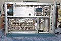
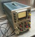
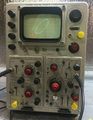
Tek 647 10a1 11b2.jpg | 647 with [[10A1]] and [[11B2]] | |||
Tek 647 right.jpg | 647 Right Side | |||
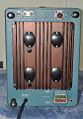
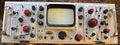
647 MOD165K.JPG | 647 with MOD165K | |||
</gallery> | </gallery> | ||
===647A=== | |||
<gallery> | |||
647a_1.jpg | 647A Front View | |||
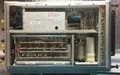
647a_2.jpg | 647A Left View | |||
647a_4.jpg | 647A Right View | |||
647a_3.jpg | 647A Rear View | |||
Tek 647a front.jpg | 647A with [[10A1]] and [[11B2|11B2A]] | |||
Tek 647a left.jpg | 647A | |||
Tek 647a rear.jpg | 647A | |||
Tek 647a rear connections.jpg | 647A rear connections | |||
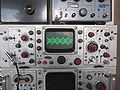
Tek 10a2a 11b2a.jpg | [[10A2 | 10A2A]] and [[11B2 | 11B2A]] in 647A | |||
Tek 647a rear2.jpg | 647A | |||
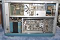
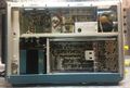
Tek 647a right internal.jpg | 647A | |||
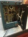
Tek 647a left internal.jpg | 647A | |||
Tek 647a rear ps.jpg | 647A | |||
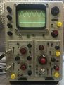
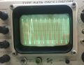
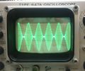
Tek 647a trace6.jpg | 647A | |||
Tek 647a trace5.jpg | 647A | |||
Tek 647a trace4.jpg | 647A | |||
Tek 647a trace3.jpg | 647A | |||
Tek 647a trace2.jpg | 647A | |||
Tek 647a trace1.jpg | 647A | |||
</gallery> | |||
===RM647=== | |||
<gallery> | |||
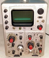
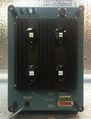
RM647_1.JPG | RM647 Front View | |||
Tek rm647.jpg | RM647 | |||
</gallery> | |||
==Components== | |||
{{Parts|647}} | |||
{{Parts|RM647}} | |||
[[Category:Introduced in 1963]] | |||
[[Category:647 series scopes]] | |||
Latest revision as of 03:42, 3 March 2024

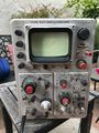
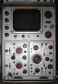
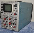
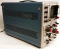
The Tektronix 647 is a 50 MHz oscilloscope with plug-ins for both vertical and horizontal deflection. It was introduced in late 1963, along with a minimal set of plug-ins, and replaced by the higher bandwidth 647A in 1967. Except for the CRT and the rectifiers in the HV power supply, the 647 is all solid state.
The original 647 project leader was Oz Svehaug in 1962. From 1963 onward, Oliver Dalton took over.
The intent was to offer a higher performance scope in a small form factor, roughly the size and weight of the 560 series. It was promoted as “ruggedized” with an extended operating temperature range, and higher shock and vibration ratings than previous lab grade instruments.
The 647 uses 10 series vertical and 11 series time base plug-ins. At introduction, the 10A2 a dual channel 50 MHz vertical, 11B1 single time base, and 11B2 dual time base were offered. The 10A1 45 MHz differential comparator was introduced in 1965, the 10A2A amplifier in 1967. The 10 and 11 series plug-ins are unique to the 647 and 647A.
Key Specifications
| Bandwidth | DC to 50 MHz with 10A2 plug-in, 45 MHz with 10A1 (35 MHz at <5 mV/div) |
|---|---|
| Rise time | 5.8 ns with 10A2, 7.8 ns with 10A1 (10 ns at <5 mV/div) |
| CRT | T6470, P31 std / P11 opt., 6 cm × 10 cm, 14 kV acceleration |
| Power | 108/115/122/216/235/244 VAC ±10%,selected via primary voltage selector and voltage range selector switches, 50 Hz to 60 Hz; 185W with 10A2 & 11B2 plug-in |
| Operating Temperature | –30 C° to +65 C° |
| Cooling | AC Fan (only in rack variant) |
| Thermal Protection | Automatic resetting thermal cutout, in case internal temperature exceeds safe operating level |
| Weight | 18.4 kg (40.5 lbs) |
Internals
Unlike the threaded knob used for retaining the 530/540 series plug-ins, the 647 uses a lever-actuated cam mechanism. The single lever both engages and disengages the plug-in with a quick, smooth motion. Many users considered it to be the best plug-in retaining system Tek had ever offered.
Unlike the 560 series where the plug-ins directly drive the CRT deflection plates, the 647 has amplifiers for both the vertical and horizontal signals in the mainframe. In addition to supporting the higher bandwidth, the amplifiers provide a normalized gain at the plug-in interface, eliminating the need to adjust the gain or sweep cal every time a plug-in was swapped.
The 647 has a 140 ns delay line between the vertical plug-in connector and the input of the vertical amplifier. The interface between the vertical plug-in and the mainframe is a 93 Ω controlled-impedance connection. This is in contrast to the 500-series scopes, which appear to the plug-in as a high impedance.
The horizontal and vertical plug-ins are not electrically interchangeable. Only a 10 series plug-in will work in the vertical compartment, and only a 11 series time base will work in the horizontal compartment. X-Y mode requires the use of the external horizontal input in an 11 series time base.
The 647 uses the T6470 CRT with electromagnetic trace rotation and 14 kV total accelerating voltage. The HV power supply contains five 5642 rectifier tubes: three for the +11.2 kV CRT anode supply, one for the -2.2 kV CRT cathode, and one for the -2.2 kV CRT grid/blanking.
The calibrator in the 647 is based on a 4 kHz crystal, which is divided down to 1 kHz ±1 Hz.
The solid extender for 647 plug-ins is the 013-077.
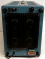
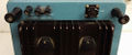
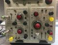
Pictures
647
-
-
647 Right Side
-
647 with MOD165K


647A
-
647A Front View
-
647A Left View
-
647A Right View
-
647A Rear View
-
-
647A
-
647A
-
647A rear connections
-
-
647A
-
647A
-
647A
-
647A
-
647A
-
647A
-
647A
-
647A
-
647A
-

647A


RM647
-
RM647 Front View
-
RM647

Components
Some Parts Used in the 647
| Part | Part Number(s) | Class | Description | Used in |
|---|---|---|---|---|
| 5642 | 154-0051-00 • 154-0079-00 | Vacuum Tube (Diode) | directly-heated high-voltage rectifier | 310 • 310A • 316 • 317 • 360 • 453 • 502 • 502A • 503 • 504 • 506 • 513 • 515 • 516 • 524 • 529 • RM529 • 533 • 533A • 535 • 536 • 543 • 543A • 543B • 545 • 545A • 545B • 547 • 551 • 555 • 556 • 560 • 561 • 561A • 561S • 564 • 567 • 570 • 575 • 581 • 581A • 585 • 585A • 647 • 647A |
| T6470 | 154-0434-00 • 154-0448-00 | CRT | CRT | 647 • 647A |
Some Parts Used in the RM647