7A42: Difference between revisions
(better 7A42 front panel photo) |
No edit summary |
||
| Line 67: | Line 67: | ||
<gallery> | <gallery> | ||
Tektronix 7A42 front.jpg | |||
Tek 7a42.jpg | Tek 7a42.jpg | ||
Tek 7a42 1.jpg | Tek 7a42 1.jpg | ||
Tek 7a42 2.jpg | Tek 7a42 2.jpg | ||
Tek 7a42 fr1.jpg | Tek 7a42 fr1.jpg | ||
Tek 7a42 fr2.jpg | Tek 7a42 fr2.jpg | ||
| Line 79: | Line 78: | ||
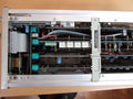
Tek 7a42 fr6.jpg | 7A42 rear view | Tek 7a42 fr6.jpg | 7A42 rear view | ||
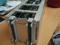
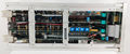
Tek 7a42 fr7.jpg | 7A42 top view | Tek 7a42 fr7.jpg | 7A42 top view | ||
</gallery> | |||
'''Internal''' | |||
<gallery> | |||
Tek 7a42 fr8.jpg | memory backup battery | Tek 7a42 fr8.jpg | memory backup battery | ||
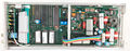
Tek 7a42 fr9.jpg | internal switch mode PSU for digital logic supplies | Tek 7a42 fr9.jpg | internal switch mode PSU for digital logic supplies | ||
| Line 84: | Line 86: | ||
Tek 7a42 fr11.jpg | amplifier board front - attenuators, amplifiers, channel switches | Tek 7a42 fr11.jpg | amplifier board front - attenuators, amplifiers, channel switches | ||
Tek 7a42 fr12.jpg | amplifier board rear - channel switches, two 15 ns delay lines | Tek 7a42 fr12.jpg | amplifier board rear - channel switches, two 15 ns delay lines | ||
Tek 7a42 13.jpg | Tek 7a42 13.jpg | ||
Tek 7a42 14.jpg | Tek 7a42 14.jpg | ||
Revision as of 06:36, 6 January 2024

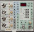
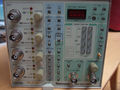
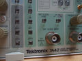
The Tektronix 7A42 is a four-channel 350 MHz plug-in for 7000-series scopes.
It was specifically designed for logic signals (TTL, ECL, CMOS) and supports triggering based on Boolean conditions of the four inputs.
A fifth trace, "Trigger View", displays the trigger function output or external clock input.
The input V/Div setting can only be seen in the mainframe's readout.
Tektronix recommended the P6131, 300 MHz, 10 MΩ ×10 probe, and the P6230, 1.5 GHz, 450/50 Ω ×10, variable-offset probe for ECL circuits.
The 067-1155-99 calibration fixture is specific to the 7A42.
Key Specifications
| Bandwidth | 350 MHz |
|---|---|
| Deflection |
|
| Input impedance | 1 MΩ // 15 pF or 50 Ω |
| Max. input voltage |
|
| Trigger level |
|
| Hysteresis | 40 mV (TTL), 8 mV (ECL) (or ×10) |
| Features |
|
| Weight | 2.8 kg / 6.2 lb |
Internals
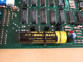
The 7A42's functions are controlled by an Intel 8085A microprocessor.
Each of the four input attenuator circuits contains five miniature relays. The bistable relay coils are wired in a 4x5 matrix.
The 7A42 contains its own switch mode PSU, based on an SG3524 controller, that generates +5 V, −2 V and −5 V from the mainframe's ±50 V rails.
See also
Pictures
-
-
-

-
-
-
-
-
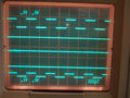
display - four signal traces plus trigger view
-
-
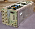
7A42 rear view
-
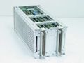
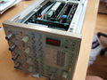
7A42 top view


Internal
-
memory backup battery
-
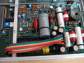
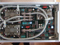
internal switch mode PSU for digital logic supplies
-
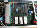
microprocessor board
-
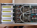
amplifier board front - attenuators, amplifiers, channel switches
-
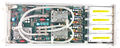
amplifier board rear - channel switches, two 15 ns delay lines
-
-
-


Components
Some Parts Used in the 7A42
| Part | Part Number(s) | Class | Description | Used in |
|---|---|---|---|---|
| 148-0145-00 | 148-0145-00 | Discrete component | miniature bi-stable relay actuator | 7A42 • 119-1517-00 |
| 155-0038-01 | 155-0038-00 • 155-0038-01 | Monolithic integrated circuit | 5-bit current source D/A converter | 7A42 • 7D13 • 7D14 • 7M13 • T4005 |
| 155-0078-00 | 155-0078-xx • 155-0273-00 • 155-0274-00 | Monolithic integrated circuit | broadband amplifier | 464 • 465 • 466 • 468 • 475 • 475A • 475M • 485 • 7834 • 7844 • 7854 • 7904 • R7903 • R7912 • 7912AD • 7912HB • 7104 • 7A16A • 7A16P • 7A24 • 7A26 • 7A42 • 067-0587-01 • 067-0680-00 • AM503 • PG502 • PG508 • DC510 • DC5010 • FG5010 |
| 155-0236-00 | 155-0236-00 | Hybrid integrated circuit | channel switch | 2445 • 2465 • 7A42 |
| ICM7218 | 156-1621-00 • 156-1622-00 | Monolithic integrated circuit | 8-digit, 7-segment LED driver | 7A42 |
| Intel 8085 | 156-1088-00 | Monolithic integrated circuit | 8-bit microprocessor | 308 • 468 • 4025 • 7A42 • 7D02 • AFG5101 • AFG5102 |