LA501: Difference between revisions
No edit summary |
No edit summary |
||
| (19 intermediate revisions by 5 users not shown) | |||
| Line 1: | Line 1: | ||
{{TM500 | mfg=Tektronix | type=LA501 | function=logic analyzer | class=logic analyzer | image=Tek la501 front.jpg | introduced=1976 | discontinued=1978 | | {{TM500 | mfg=Tektronix | type=LA501 | function=logic analyzer | class=logic analyzer | image=Tek la501 front.jpg | introduced=1976 | discontinued=1978 | | ||
manuals= | designers= |manuals= | ||
* [ | * [[Media:070-1967-00.pdf|Tektronix LA 501 with Options Manual]] | ||
* [ | * [[Media:070-2047-00.pdf|Tektronix LA 501 Operators Manual]] | ||
* [[ | * [[Media:070-2169-00.pdf|Tektronix LA501W Operators Manual]] | ||
* [[Media:la501w.pdf|Tektronix LA501 and LA501W catalog pages]] | |||
}} | }} | ||
It has a cable-attached, passive 16-channel probe, the [[P6450]], and outputs analog X/Y/Z signals for an external oscilloscope or X/Y monitor. Alternatively, channels 0-3 can be switched to four [[BNC connector]] inputs with 1 MΩ impedance intended for external ×10 probes. | |||
The '''LA501W''' was a bundle of the LA501 with a [[WR501]] connected internally | The '''LA501W''' was a bundle of the LA501 with a [[WR501]] connected internally to provide word recognition trigger as well as data acquisition. In this case, there is no [[P6450]] probe; instead, one or two [[P6451]] probes are attached to the WR501. | ||
The LA501 provides only a timing diagram with clock tick marks on the traces, and analog zoom/pan controls for focusing on a particular trace or detail. | |||
Each channel can be positioned anywhere vertically to allow for timing comparisons. | |||
{{BeginSpecs}} | {{BeginSpecs}} | ||
| Line 13: | Line 17: | ||
{{Spec | Sampling rate | up to 50 MHz (100 MHz @ 4ch) }} | {{Spec | Sampling rate | up to 50 MHz (100 MHz @ 4ch) }} | ||
{{EndSpecs}} | {{EndSpecs}} | ||
==Links== | |||
{{Documents|Link=LA501}} | |||
==Pictures== | ==Pictures== | ||
<gallery> | <gallery> | ||
Tek la501 front3.jpg|LA501 | |||
Tek la501 front.jpg|LA501 | Tek la501 front.jpg|LA501 | ||
Tek la501 w probe.jpg|LA501 | Tek la501 w probe.jpg|LA501 | ||
Tek dl502 wr501 la501w.jpg| [[DL502]], [[WR501]], and LA501W | Tek dl502 wr501 la501w.jpg| [[DL502]], [[WR501]], and LA501W | ||
LA501W-TM515.jpg | LA501W (including WR501) with [[SC502]] scope in a [[TM515]] mainframe | |||
Tek la501 bc1.png | |||
Tek la501 bc2.png | |||
Tek la501 bc3.png | [[012-0725-01]] Clock Access Conversion Kit for the LA501W | |||
</gallery> | </gallery> | ||
==Components== | |||
{{Parts|LA501}} | |||
Revision as of 09:05, 19 November 2023
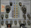
The Tektronix LA501 is a logic analyzer plug-in for the TM500 system.
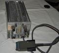
It has a cable-attached, passive 16-channel probe, the P6450, and outputs analog X/Y/Z signals for an external oscilloscope or X/Y monitor. Alternatively, channels 0-3 can be switched to four BNC connector inputs with 1 MΩ impedance intended for external ×10 probes.
The LA501W was a bundle of the LA501 with a WR501 connected internally to provide word recognition trigger as well as data acquisition. In this case, there is no P6450 probe; instead, one or two P6451 probes are attached to the WR501.
The LA501 provides only a timing diagram with clock tick marks on the traces, and analog zoom/pan controls for focusing on a particular trace or detail. Each channel can be positioned anywhere vertically to allow for timing comparisons.
Key Specifications
| Memory | 4096 bit (4ch/1024 bit, 8ch/512bit or 16ch/256bit) |
|---|---|
| Sampling rate | up to 50 MHz (100 MHz @ 4ch) |
Links
Documents Referencing LA501
Pictures
-
LA501
-
LA501
-
LA501
-
-
-
012-0725-01 Clock Access Conversion Kit for the LA501W
Components
Some Parts Used in the LA501
- (no results)


