DC505A: Difference between revisions
m (typo) |
No edit summary |
||
| (2 intermediate revisions by the same user not shown) | |||
| Line 3: | Line 3: | ||
* [[Media:070-1984-00.pdf|Tektronix DC505A Manual]] (OCR) | * [[Media:070-1984-00.pdf|Tektronix DC505A Manual]] (OCR) | ||
}} | }} | ||
The predecessor of the DC505A was the [[DC505]]. | |||
{{BeginSpecs}} | {{BeginSpecs}} | ||
{{Spec | Frequency range | 0 Hz (DC coupled) / 10 Hz (AC coupled) to 225 MHz }} | {{Spec | Frequency range | 0 Hz (DC coupled) / 10 Hz (AC coupled) to 225 MHz }} | ||
| Line 67: | Line 68: | ||
==Internals== | ==Internals== | ||
The manual warns that if multiple 505As with serial numbers B010630 are installed in a mainframe, the mainframe needs | The manual warns that if multiple 505As with serial numbers B010630 and above are installed in low-power compartments of a TM500 mainframe, | ||
the mainframe needs to be modified to allow for the extra current draw. | |||
The required modifications are described in the DC505A manual. | |||
An internal VCO, phase-locked to the 1 MHz master, produces a 100 MHz input to the counter chain for timing measurements. | An internal VCO, phase-locked to the 1 MHz master, produces a 100 MHz input to the counter chain for timing measurements. | ||
| Line 79: | Line 82: | ||
<gallery> | <gallery> | ||
Tek dc505a.jpg | DC505A | Tek dc505a.jpg | DC505A | ||
DC 505A-1 B011xxx.jpg | DC505A | |||
</gallery> | </gallery> | ||
==Components== | ==Components== | ||
{{Parts|DC505A}} | {{Parts|DC505A}} | ||
Latest revision as of 14:43, 15 February 2024
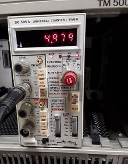
The Tektronix DC505A is a 225 MHz counter/timer plug-in for the TM500 system.
The predecessor of the DC505A was the DC505.
Key Specifications
| Frequency range | 0 Hz (DC coupled) / 10 Hz (AC coupled) to 225 MHz |
|---|---|
| Sensitivity | 50 mVRMS to 150 MHz, 100 mVRMS to 225 MHz (sine) |
| Resolution | 7 digits max. |
| Gate time | 0.01 s to 10 s in decade steps |
| Stability | Standard: 1×10⁻⁵; Opt.1: 5×10⁻⁷ (0°C to +50°C, after 30 min warm-up) |
| Long-term drift | Standard: 1×10⁻⁵ per month; Opt.1: 5×10⁻⁷ per month |
| Features |
|
| Options |
|
Links
Documents Referencing DC505A
Rear Interface
| Connector Pin | Signal | Connector Pin | Signal |
|---|---|---|---|
| 27B | DP5 (Opt.4 only) | 27A | Internal Scan Clock Disable |
| 26B | Manual Start-Stop | 26A | /RESET |
| 25B | Internal Scan Clock Out | 25A | Time Slot Zero |
| 24B | Internal Scan Clock Out | ||
| 23B | Overflow | ||
| 22A | Trig Level Out | ||
| 21B | BCD output 2 | ||
| 20B | BCD output 8 | 20A | BCD output 4 |
| 19B | Data Good | 19A | BCD output 1 |
| 18B | DP4 (Opt.4 only) | ||
| 17B | Ch B Input | 17A | Ch A GND |
| 16B | Ch B GND | 16A | Ch A Input |
| 15B | DP3 (Opt.4 only) | 15A | DP1 (Opt.4 only) |
| 14B | DP2 (Opt.4 only) | 14A | Ext Clock Input / 1 MHz Out |
Data is output serially by digit.
The rear interface inputs are selected by pulling out the LEVEL knob.
Internals
The manual warns that if multiple 505As with serial numbers B010630 and above are installed in low-power compartments of a TM500 mainframe, the mainframe needs to be modified to allow for the extra current draw. The required modifications are described in the DC505A manual.
An internal VCO, phase-locked to the 1 MHz master, produces a 100 MHz input to the counter chain for timing measurements.
The DC505A uses a mix of ECL and TTL dividers and logic, and a Mostek MK5007 four-decade counter/latch/multiplexer (U700). Unlike the similarly-specified 7D15, it employs no Tek made custom ICs. The first counter decade is implemented as a divide-by-2 ECL flip-flop (U350, MC1670) followed by a five-stage ring counter made with MC10131 ECL flipflops, and some logic to BCD-encode the count result. A similar circuit exists in the reference divider chain.
In the power supply, the +5 V section, controlled by a 723, uses the mainframe's NPN pass transistor and includes a zener/SCR crowbar circuit. A discrete regulator using the PNP pass transistor produces - V from the -33 V rail.
Pictures
-
DC505A
-
DC505A
Components
Some Parts Used in the DC505A
| Part | Part Number(s) | Class | Description | Used in |
|---|---|---|---|---|
| 2N4249 | 151-0342-00 | Discrete component | PNP Si low noise amp. | DC501 • DC502 • DC503 • DC503A • DC504 • DC504A • DC505 • DC505A • DC508 • DC508A • DC509 • DC510 |
| Mostek MK5007 | 156-0409-00 | Monolithic integrated circuit | four-decade BCD counter with latches and output multiplexer | 213 • DC505 • DC505A |

