Cam switches: Difference between revisions
No edit summary |
No edit summary |
||
| Line 26: | Line 26: | ||
Some switch assemblies also have contacts on the opposite side of the PCB, actuated via small plastic plungers. | Some switch assemblies also have contacts on the opposite side of the PCB, actuated via small plastic plungers. | ||
Finally, the [[067-0587-02]] plug-in uses a special [[Media:7104_maintenance.pdf|elastomer-based cam switch]]. | Finally, the [[067-0587-02]] plug-in uses a special [[Media:7104_maintenance.pdf|elastomer-based cam switch]]. | ||
{{PatentLinks|Cam switches}} | |||
==Maintenance== | ==Maintenance== | ||
Latest revision as of 13:25, 12 July 2024
Cam switches are used in many Tek instruments from the late 1960s to the early 1990s, particularly in 7000-series plug-ins, but also in TM500 equipment and 400-series portable scopes.
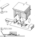
The lobes on the rotary cam encode the lookup table of which contacts should be open or closed in each rotational position of the shaft, which is typically rotated by a knob on the front panel of the instrument. A benefit of this design is low parasitics compared to traditional rotary wafer switches.
The original idea for this switch type is credited to Howard Vollum - see Patent 3,562,464 Cam actuated switch having movable and fixed contacts on circuit board (Vollum, Verhoef, Sprando). Ken Holland was also involved with the development of cam switches at Tek.
From On The History and Environment of Tektronix:
So, one day, Howard said, "the plug-ins will be 5¼ inches in height."
Oliver Dalton recalls the decision to reduce the plug-in height as a traumatic one: "The decision set us back at least one year for the height decision required three major electro-mechanical component efforts in addition to the IC read-out effort: 1) new lit push-buttons ... we needed 25 on a panel; 2) cam switches - these were Howard's ideas ... we needed them to be small and reasonably cheap; 3) relays ... we needed them to be small and reliable. We then largely had to make do with other available parts, like potentiometers.
[...]
Then Howard Vollum made the decision that Tek would develop its own switches, and Tony Sprando, Bill Verhoef, and Howard jointly developed the cam switch. The design ideas emerged from a "a lot of way-out brainstroming. "Howard played a key role by taking an "unlimited funds, the sky's the limit" attitude, while the other members would bring the ideas back to reality.
Once the concepts were established, the manufacturing problems began. The prototypes had been made on numerically controlled machines, and the proposal was now to cast key pieces in plastic. But the Plastics Group said it could not be done. Finally, Tony came up with a four-piece die design that would do the job (previous approaches to die design had assumed there would be only two pieces). The four-piece die was the critical breakthrough which then made production possible at a reasonable cost.
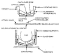
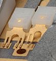
There were different forms of contact fingers in use. The basic type, as described in the patent drawings (also in use in the back-lit pushbuttons) have a contact spring on a post soldered into the board. Another type, used in high-frequency attenuators types, has a spring riveted to the board, with a small multi-fingered, gold-plated contact spring element isolated by a molded plastic assembly. In these, the spring is typically grounded, and the isolated contact fingers bridge adjacent pads when actuated. Some switch assemblies also have contacts on the opposite side of the PCB, actuated via small plastic plungers. Finally, the 067-0587-02 plug-in uses a special elastomer-based cam switch.
Patents that may apply to Cam switches
| Page | Title | Inventors | Filing date | Grant date | Links |
|---|---|---|---|---|---|
| Patent US 3562464A | Cam actuated switch having movable and fixed contacts on circuit board | Howard Vollum • Willem H Verhoef • Tony Sprando | 1968-10-07 | 1971-02-09 | Cam switches • 2101 • 2701 • 2703 • 432 • 434 • 465 • 475 • 5A15N • 5A18N • 5A20N • 5A21N • 5A38 • 5A45 • 5B10N • 5B12N • 7A15 • 7A16A • 7A18 • 7A19 • 7A24 • 7A26 • 7B10 • 7B15 • 7B50 • 7B51 • 7B52 • 7B53A • 7B50A • 7B70 • 7B71 • 7B80 • 7B85 • 7B87 • 7B92 • 7B92A • 7D01 • 7D12 • 7D15 • 7J20 • 7S12 • 7T11 • 7T11A • AF501 • AM502 • AM503 • DC502 • DC503 • DC504 • DC505 • DM501 • DM502 • FG501 • FG501A • FG502 • FG503 • FG504 • FG507 • PG501 • PG502 • PG505 • PG506 • PG506A • PG508 • TG501 • SC502 • SC503 • SC504 |
Maintenance
- For cleaning, Tek recommends swiping paper soaked in isopropyl alcohol between the contacts and pads.
- 040-0541-00 Cam switch repair kit (1970)
- TekScope Vol. 9 No. 1, 1977 p.14: Cam switch cleaning tips
- Tektronix cam switch repair manual
Pictures
Drawings
-
Core of the cam switch
-
Basic switch contact with solder post (shown in alignment jig)
-
Isolated contact type used in attenuators
-
Elastomer contact used in 067-0587-02
Photos


