3A9: Difference between revisions
No edit summary |
mNo edit summary |
||
| (14 intermediate revisions by 4 users not shown) | |||
| Line 1: | Line 1: | ||
{{Plugin Sidebar | {{Plugin Sidebar | ||
|manufacturer=Tektronix | |||
summary=1 MHz | |series=560-series scopes | ||
image=3a9 front. | |type=3A9 | ||
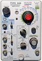
caption=Tektronix 3A9 front | |summary=1 MHz differential amplifier plug-in | ||
|image=Tek 3a9 front.jpeg | |||
|caption=Tektronix 3A9 front | |||
introduced=1969 | | |introduced=1969 | ||
discontinued=1974 | | |discontinued=1974 | ||
manuals= | |designers=Val Garuts | ||
* [ | |manuals= | ||
* [[Media:070-0913-00.pdf|Tektronix 3A9 Manual]] (PDF) | |||
* [[Media:Tek 3a9 fcp april 1969.pdf|Tektronix 3A9 Factory Calibration Procedure, April 1969]] | |||
}} | }} | ||
The '''Tektronix 3A9''' is a differential amplifier plug-in [[introduced in 1969]] for [[560-series scopes]]. | The '''Tektronix 3A9''' is a differential amplifier plug-in [[introduced in 1969]] for [[560-series scopes]]. | ||
It shares similarities with the [[7A22]] from the [[7000-series scopes|7000 series]] and [[ | It shares similarities with the [[3A10]] transducer amplifier and the [[7A22]] from the [[7000-series scopes|7000 series]] and [[5A22N]] from the [[5000-series scopes]]. | ||
The 3A9 features a variable high-frequency cut-off from 100 Hz to 1 MHz and a variable low-frequency | The 3A9 features a variable high-frequency cut-off from 100 Hz to 1 MHz and a variable low-frequency cut-off from DC to 10 kHz. | ||
cut-off from DC to 10 kHz. When DC coupled, the 3A9 provides a variable offset voltage. | When DC coupled, the 3A9 provides a variable offset voltage. The common mode rejection is 100,000:1. | ||
The common mode rejection is 100,000:1. | |||
{{BeginSpecs}} | {{BeginSpecs}} | ||
| Line 42: | Line 43: | ||
The differential amplifier design is a variant of the [[1A7A]] circuit, also used with modifications | The differential amplifier design is a variant of the [[1A7A]] circuit, also used with modifications | ||
in the [[7A22]], [[5A22N]], [[AM502]] and [[ | in the [[3A10]], [[7A22]], [[5A22N]] oscilloscope plug ins, and [[5030]]/[[5031]] scopes. The [[AM502]] and the [[26A2]] for the [[2601]] mainframe use BJTs for the offset current sources instead of JFETs. The [[26A2]] adds a common mode signal circuit which is connected to a LEMO probe connector. | ||
The 3A9 provides differential high-impedance voltage inputs and an AC current probe input | The 3A9 provides differential high-impedance voltage inputs and an AC current probe input | ||
for use with | for use with 125-turn probes ([[P6021]] or [[P6019]]). | ||
The front-end of the 3A9 starts with a differential pair formed by the two N-channel JFETs in | The front-end of the 3A9 starts with a differential pair formed by the two N-channel JFETs in a [[151-1027-00]], Q133. | ||
==Pictures== | ==Pictures== | ||
| Line 59: | Line 60: | ||
Tek 3a9 preamp.png|Preamp (front-end) schematic | Tek 3a9 preamp.png|Preamp (front-end) schematic | ||
</gallery> | </gallery> | ||
==Components== | |||
{{Parts|3A9}} | |||
[[Category:560 series plugins]] | [[Category:560 series plugins]] | ||
[[Category:Differential amplifiers]] | [[Category:Differential amplifiers]] | ||
Latest revision as of 07:16, 28 November 2023

The Tektronix 3A9 is a differential amplifier plug-in introduced in 1969 for 560-series scopes. It shares similarities with the 3A10 transducer amplifier and the 7A22 from the 7000 series and 5A22N from the 5000-series scopes.
The 3A9 features a variable high-frequency cut-off from 100 Hz to 1 MHz and a variable low-frequency cut-off from DC to 10 kHz. When DC coupled, the 3A9 provides a variable offset voltage. The common mode rejection is 100,000:1.
Key Specifications
| Bandwidth | 1 MHz, LF limit switchable DC, 0.1 Hz to 10 kHz in ×10 steps, HF limit switchable 100 Hz to 1 MHz in ×3/×10 steps |
|---|---|
| Deflection | 10 μV/Div to 10 V/Div in 1–2–5 sequence |
| Input impedance | 1 MΩ // 47 pF (either input) |
| Signal ranges |
| Range | Differential signal | DC Offset | Common mode |
|---|---|---|---|
| 10 μV/Div to 10 mV/Div | ±1 V | ±1 V | ±10 V |
| 20 mV/Div to 0.1 V/Div | ±10 V | ±10 V | ±100 V |
| 0.2 V/Div to 1 V/Div | ±100 V | ±100 V | ±500 V |
| 2 V/Div to 10 V/Div | ±1000 V | ±1000 V | ±500 V |
Internals
The differential amplifier design is a variant of the 1A7A circuit, also used with modifications in the 3A10, 7A22, 5A22N oscilloscope plug ins, and 5030/5031 scopes. The AM502 and the 26A2 for the 2601 mainframe use BJTs for the offset current sources instead of JFETs. The 26A2 adds a common mode signal circuit which is connected to a LEMO probe connector.
The 3A9 provides differential high-impedance voltage inputs and an AC current probe input for use with 125-turn probes (P6021 or P6019).
The front-end of the 3A9 starts with a differential pair formed by the two N-channel JFETs in a 151-1027-00, Q133.
Pictures
-
-

-
-
-

-

-
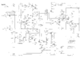
Preamp (front-end) schematic


Components
Some Parts Used in the 3A9
| Part | Part Number(s) | Class | Description | Used in |
|---|---|---|---|---|
| 151-0261-00 | 151-0261-00 | Discrete component | dual PNP transistor | AM501 • AM502 • CG5001 • CG551AP • FG501 • FG502 • FG503 • OF150 • OF151 • OF152 • OF235 • OS261 • RM502A • R1140 • R5030 • R5031 • R7912 • 067-0679-00 • 067-0807-00 • 1101 • 1140A • 1141 • 1142 • 1350 • 145 • 1450 • 1480 • 1481 • 1482 • 1485 • 1501 • 1801 • 1900 • 1910 • 1980 • 213 • 26A1 • 26A2 • 2620 • 285 • 3A9 • 3A10 • 3S1 • 3S2 • 3S5 • 3S6 • 432 • 434 • 4501 • 454 • 4601 • 4602 • 4610 • 4612 • 4620 • 4632 • 4634 • 4701 • 475 • 492 • 492A • 492AP • 494 • 494P • 496 • 496P • 5A13N • 5A20N • 5A21N • 5A22N • 5A26 • 5L4N • 502A • 5030 • 5031 • 576 • 690SR • 7A22 • 7A29 • 7B51 • 7B71 • 7J20 • 7L5 • 7S11 • 7S12 • 7912AD |
| 151-1027-00 | 151-1027-00 | Discrete component | dual N-channel JFET | 5031 • 3A9 • AM502 |