TR502: Difference between revisions
No edit summary |
No edit summary |
||
| (26 intermediate revisions by 3 users not shown) | |||
| Line 1: | Line 1: | ||
* [ | {{TM500 | mfg=Tektronix | type=TR502 | function=1.8 GHz tracking generator | class=RF generator | image=Tek tr502.jpg | introduced=1976 | discontinued=1988 | ||
|designers=Fred Telewski;Glenn Bateman;Michael McMahon;David Morton;Phillip Snow;Carlos Beeck;Jack McCabe;Leighton Whitsett; | |||
|manuals= | |||
* [[Media:070-1735-00.pdf|Tektronix TR502 Manual]] (OCR) | |||
}} | |||
The TR502 is intended to work with the [[7L13]] and [[7L14]] spectrum analyzer plugins from the 7000 series. It also works with a [[7L12]]. | |||
The [[TR501]] and TR502 are essentially the same instrument with the exception of the output attenuators and logic interface in the TR502, which adds dot marker support for the 7L13 via the TRACK GEN LOGIC connector. A 012-0648-00 cable with [[LEMO_S-series_connector|6-pin LEMO Connectors]] is required for this functionality. | |||
The [[TR503]] is similar but has different oscillator and intermediate frequencies (see link). | |||
<blockquote> | |||
Freel Telewski was Program Manager for the TR502 projcct. Assisting in electrical designe were Glenn Batenman, Michael McMahon, David Morton, and Phillip Snow. The mechanical design team included Carlos Beeck, Jack McCabe, and Leighton Whitsett. | |||
</blockquote> | |||
{{BeginSpecs}} | |||
{{Spec | Frequency range | 100 kHz to 1.8 GHz }} | |||
{{Spec | Maximum output level | 0 dBm ±0.5 dB }} | |||
{{Spec | Level range | 0 to –59 dBm }} | |||
{{Spec | Level flatness | ±0.65 dB}} | |||
{{EndSpecs}} | |||
==Compatible Counters== | |||
The TR502 provides an auxiliary RF output to be used with counters. For accurate measurement of the marker frequency while sweeping, the counter needs to be gated from the TR502 and [[7L13]]. Compatible counters are the [[DC508]] Option 7 or a [[DP501]] prescaler combined with a [[DC509]], [[DC5009]], [[DC510]], or [[DC5010]]. For the elaborate interconnects required see the figure below. | |||
==Links== | |||
* [https://www.radiomuseum.org/r/tektronix_tracking_generator_tr502.html Tektronix TR502 @ radiomuseum.org] | |||
* [http://www.ko4bb.com/doku2015/doku.php?id=test_equipment:tracking_generator_-_convert_tr-502_to_tr-503_configuration Converting a TR502 to a TR503 configuration] | |||
{{Documents|Link=TR502}} | |||
{{PatentLinks|TR502}} | |||
==Prices== | |||
{| class="wikitable" | |||
|- | |||
! Year | |||
! 1976 | |||
! 1980 | |||
! 1988 | |||
|- | |||
! Catalog price | |||
| align="right" | $4,500 | |||
| align="right" | $5,220 | |||
| align="right" | $7,080 | |||
|- | |||
! In 2023 Dollars | |||
| align="right" | $24,300 | |||
| align="right" | $19,500 | |||
| align="right" | $18,400 | |||
|- | |||
|} | |||
According to an [[Media:Tek Schottky Diodes Memo rot.pdf|internal memo]], in 1979 annual sales were estimated at 42 units. | |||
==Pictures== | |||
<gallery> | <gallery> | ||
Tek tr502 1.JPG | |||
Tek tr502 2.JPG | |||
Tek tr502 3.JPG | |||
Tek tr502.jpg | |||
TR502-block-diagram.jpg | TR502 block diagram | |||
TR502_DP501_Interconnect.png | Rear interface interconnects required for pairing with [[DP501]] and compatible counter. | |||
</gallery> | </gallery> | ||
==Components== | |||
{{Parts|TR502}} | |||
Latest revision as of 05:34, 6 October 2024
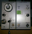
The Tektronix TR502 is a 1.8 GHz tracking generator plug-in for the TM500 system.
The TR502 is intended to work with the 7L13 and 7L14 spectrum analyzer plugins from the 7000 series. It also works with a 7L12.
The TR501 and TR502 are essentially the same instrument with the exception of the output attenuators and logic interface in the TR502, which adds dot marker support for the 7L13 via the TRACK GEN LOGIC connector. A 012-0648-00 cable with 6-pin LEMO Connectors is required for this functionality. The TR503 is similar but has different oscillator and intermediate frequencies (see link).
Freel Telewski was Program Manager for the TR502 projcct. Assisting in electrical designe were Glenn Batenman, Michael McMahon, David Morton, and Phillip Snow. The mechanical design team included Carlos Beeck, Jack McCabe, and Leighton Whitsett.
Key Specifications
| Frequency range | 100 kHz to 1.8 GHz |
|---|---|
| Maximum output level | 0 dBm ±0.5 dB |
| Level range | 0 to –59 dBm |
| Level flatness | ±0.65 dB |
Compatible Counters
The TR502 provides an auxiliary RF output to be used with counters. For accurate measurement of the marker frequency while sweeping, the counter needs to be gated from the TR502 and 7L13. Compatible counters are the DC508 Option 7 or a DP501 prescaler combined with a DC509, DC5009, DC510, or DC5010. For the elaborate interconnects required see the figure below.
Links
Documents Referencing TR502
Prices
| Year | 1976 | 1980 | 1988 |
|---|---|---|---|
| Catalog price | $4,500 | $5,220 | $7,080 |
| In 2023 Dollars | $24,300 | $19,500 | $18,400 |
According to an internal memo, in 1979 annual sales were estimated at 42 units.
Pictures
-
-
-
-
-
TR502 block diagram
-
Rear interface interconnects required for pairing with DP501 and compatible counter.
Components
Some Parts Used in the TR502
| Part | Part Number(s) | Class | Description | Used in |
|---|---|---|---|---|
| 155-0133-00 | 155-0133-00 | Hybrid integrated circuit | TR502 |


