W: Difference between revisions
Vintage dave (talk | contribs) mNo edit summary |
No edit summary |
||
| (27 intermediate revisions by 6 users not shown) | |||
| Line 1: | Line 1: | ||
{{Plugin Sidebar | {{Plugin Sidebar | ||
|manufacturer=Tektronix | |||
summary=8-23 MHz differential comparator | | |series=500-series scopes | ||
image= | |type=Type W | ||
caption=Type W front view| | |summary=8-23 MHz differential comparator | ||
introduced=1965 | | |image=Tek_Type_W_Front–Tight.jpg | ||
discontinued=1974 | | |caption=Type W front view | ||
|introduced=1965 | |||
manuals= | |discontinued=1974 | ||
* [ | |designers=John Horn | ||
* [[Media:070- | |manuals= | ||
* [ | * [[Media:070-432.pdf|Tektronix Type W Manual]] (11MB) | ||
* [[Media:Tek type w fcp jan 1969.pdf|Tektronix Type W Factory Calibration Procedure, January 1969 ( | * [[Media:070-432_Schematic_SN3270up.pdf|Tektronix Type W Schematics Color for SN 3270 up]] (10MB) | ||
* [[Media:Tek type w fcp no ocr.pdf|Tektronix Type W Factory Calibration Procedure, March 1969 ( | * [[Media:070-1109-00.pdf|Tektronix Type W SN 7000-up Manual]] (OCR) | ||
<!-- * [[Media:tek_type_w_schem_only.pdf|Tektronix Type W Schematics Only (PDF, OCR)]] --> | * [[Media:Tek type w fcp jan 1969.pdf|Tektronix Type W Factory Calibration Procedure, January 1969]] (OCR) | ||
* [[Media:Tek type w fcp no ocr.pdf|Tektronix Type W Factory Calibration Procedure, March 1969]] (OCR) | |||
* [[Media:Tek type w cal outline.pdf|Tektronix Type W Calibration Outline]] (OCR) | |||
<!-- | |||
* [http://w140.com/tek_type_w_schematics.pdf Tektronix Type W Schematics Only (PDF)] | |||
* [http://w140.com/mmm/tek-w.pdf Tektronix Type W Manual (37MB, PDF)] | |||
* [[Media:tek_type_w_schem_only.pdf|Tektronix Type W Schematics Only (PDF, OCR)]] | |||
--> | |||
}} | }} | ||
The '''Tektronix Type W''' is a differential comparator plug-in amplifier for [[500-series scopes]] | The '''Tektronix Type W''' is a differential comparator plug-in amplifier for [[500-series scopes]], designed by [[John Horn]]. | ||
{{BeginSpecs}} | |||
{{Spec | Deflection | 1 mV/Div to 50 V/Div, 1–2–5 (6-position) and 4-position decade attenuator }} | |||
{{Spec | Input impedance | 1 MΩ // 20 pF (either input) }} | |||
{{Spec | Bandwidth | 26 MHz (23 MHz below S/N 7000) @ 50 mV/cm; 8 MHz @ 1 mV/cm }} | |||
{{Spec | Common Mode Range | ±15 V after INPUT ATTEN }} | |||
{{Spec | CMRR | DC Coupled: 20000:1 DC to 20 kHz, 500:1 at 500 kHz; AC Coupled: 1000:1 at 60 Hz }} | |||
{{Spec | Signal ranges | }} | |||
{| class="wikitable" border=1 style="margin-left: 8em;" | | |||
!Maximum Input Voltage (S/N 7000-up) | |||
|- | |||
| DC Coupled || 350 V | |||
|- | |||
| AC Coupled || 500 V | |||
|- | |||
!Maximum Input Voltage (S/N 101-6999) | |||
|- | |||
| INPUT ATTEN = 1 || 15 V | |||
|- | |||
| INPUT ATTEN = 10 || 150 V | |||
|- | |||
| INPUT ATTEN = 100 || ±350 V (DC Coupled); 500 V (AC Coupled) | |||
|- | |||
| INPUT ATTEN = 1000 || ±350 V (DC Coupled); 500 V (AC Coupled) | |||
|- | |||
|} | |||
Type W is faster (bandwidth 23 MHz to 8 MHz depending on gain) than its [[Z|Type Z]] predecessor, and it extends performance in terms of sensitivity, reaching 1 mV/div. | |||
It achieves 20,000 to 1 common-mode rejection at DC and low frequencies. | |||
{{EndSpecs}} | |||
==Links== | |||
{{Documents|Link=W}} | |||
==Calibration Fixture== | |||
:[[067-0503-00]] Precision DC Divider, 10x & 100x | |||
==Operation== | |||
Type W has two signal inputs, "A" and "B", and a built in precision variable voltage supply, "V<sub>C</sub>", | Type W has two signal inputs, "A" and "B", and a built in precision variable voltage supply, "V<sub>C</sub>", | ||
which is controlled by a ten-turn pot and can vary from either −1.1 V to +1.1 V or −11 V to +11 V. | which is controlled by a ten-turn pot and can vary from either −1.1 V to +1.1 V or −11 V to +11 V. | ||
| Line 28: | Line 69: | ||
An output of V<sub>C</sub> is provided on the front panel for precision measurements. | An output of V<sub>C</sub> is provided on the front panel for precision measurements. | ||
Unlike the Type Z, Type W has two gain axes: a decade attenuator and a 1−2−5−10−20−50 selector, | Unlike the Type Z, Type W has two gain axes: a decade attenuator and a 1−2−5−10−20−50 selector, reminiscent of [[D|Type D]] from ten years before. | ||
reminiscent of [[D|Type D]] from ten years before. | |||
Type W is the only letter-series plug-in with an "infinite resistance" input mode selectable at the front panel. | Type W is the only letter-series plug-in with an "infinite resistance" input mode selectable at the front panel. | ||
([[1A5 | (Types [[1A5]] and [[1A7]] have an internal jumper that can be cut.) | ||
Early production Type W in a [[556]] mainframe won't meet spec for overdrive recovery time, because an overdriven W passes enough common-mode to the mainframe vertical amp to saturate it. | |||
At S/N 3270, this was fixed, by adding another stage to attenuate CM. The new "output amp" circuit board clips onto the rear bulkhead; significant hand mods are required on the chassis. | |||
This was also offered as Modification kit 040-0447-00 to retrofit existing instruments. | |||
In the letter-series timeline of differential comparators, Type W, [[introduced in 1965]], | Type W was created with a pair of type [[8056]] [[Nuvistor|Nuvistors]] in the front end. In 1971 (S/N 7000), following the lead of Type [[1A7]], the Nuvistors were replaced by JFETs to reduce drift. | ||
follows [[Z|Type Z]] and precedes [[1A5|Type 1A5]]. | Mod kit 040-0590-00 was offered for existing instruments. | ||
In the letter-series timeline of differential comparators, Type W, [[introduced in 1965]], follows [[Z|Type Z]] and precedes [[1A5|Type 1A5]]. | |||
Type W uses three type [[8416]] tubes, the 12V version of the [[6DJ8]]. | |||
[[ | |||
==Pictures== | ==Pictures== | ||
<gallery> | <gallery> | ||
Tek_Type_W_Front.jpg|Front View | |||
Tek_Type_W_Right.jpg|Right View | |||
Tek_Type_W_Left.jpg|Left View | |||
Tek_Type_W_Top.jpg|Top View | |||
Tek_Type_W_Bottom.jpg|Bottom View | |||
Tek w block.png|Block Diagram | |||
Type_w_front.jpg|Front view. | Type_w_front.jpg|Front view. | ||
Type_w_topleft.jpg|Top-left view. | Type_w_topleft.jpg|Top-left view. | ||
Type_w_bottom.jpg|Bottom view. | Type_w_bottom.jpg|Bottom view. | ||
Tek w differential comparator.png|Differential Comparator, initial version | |||
Tek w differential comparator.png|Differential Comparator | |||
Tek w input attenuators.png|Input Attenuators | Tek w input attenuators.png|Input Attenuators | ||
Tek w switching diagram.png|Switching Diagram | Tek w switching diagram.png|Switching Diagram | ||
| Line 57: | Line 106: | ||
Tek type w a phase 5.jpg|A-phase (prototype) Type W | Tek type w a phase 5.jpg|A-phase (prototype) Type W | ||
</gallery> | </gallery> | ||
==Components== | |||
{{Parts|W}} | |||
[[Category:500 series plugins]] | [[Category:500 series plugins]] | ||
[[Category:Differential amplifiers]] | |||
Latest revision as of 16:37, 9 March 2024
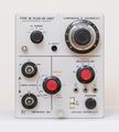
The Tektronix Type W is a differential comparator plug-in amplifier for 500-series scopes, designed by John Horn.
Key Specifications
| Deflection | 1 mV/Div to 50 V/Div, 1–2–5 (6-position) and 4-position decade attenuator |
|---|---|
| Input impedance | 1 MΩ // 20 pF (either input) |
| Bandwidth | 26 MHz (23 MHz below S/N 7000) @ 50 mV/cm; 8 MHz @ 1 mV/cm |
| Common Mode Range | ±15 V after INPUT ATTEN |
| CMRR | DC Coupled: 20000:1 DC to 20 kHz, 500:1 at 500 kHz; AC Coupled: 1000:1 at 60 Hz |
| Signal ranges |
| Maximum Input Voltage (S/N 7000-up) | |
|---|---|
| DC Coupled | 350 V |
| AC Coupled | 500 V |
| Maximum Input Voltage (S/N 101-6999) | |
| INPUT ATTEN = 1 | 15 V |
| INPUT ATTEN = 10 | 150 V |
| INPUT ATTEN = 100 | ±350 V (DC Coupled); 500 V (AC Coupled) |
| INPUT ATTEN = 1000 | ±350 V (DC Coupled); 500 V (AC Coupled) |
Type W is faster (bandwidth 23 MHz to 8 MHz depending on gain) than its Type Z predecessor, and it extends performance in terms of sensitivity, reaching 1 mV/div. It achieves 20,000 to 1 common-mode rejection at DC and low frequencies.
Links
Documents Referencing W
| Document | Class | Title | Authors | Year | Links |
|---|---|---|---|---|---|
| Tekscope 1970 V2 N5 Oct 1970.pdf | Article | Amplitude Measurement to Better Than 1% | 1970 | 1S1 • 7503 • 7A13 • 1A5 • W • 3A7 | |
| Tekscope 1972 V4 N5 Sep 1972.pdf | Article | A Practical Approach to Differential Amplifiers and Measurements | Fred Beckett | 1972 | 112 • 11A33 • 1A5 • 1A6 • 1A7 • 1A7A • 26A2 • 3A9 • 5A22N • 7A13 • 7A22 • AM502 • D • E • G • P6055 • P6046 • W • Z |
| Tekscope 1972 V4 N6 Nov 1972.pdf | Article | Differential Amplifiers and Measurements, Part 2 | Fred Beckett | 1972 | 112 • 11A33 • 1A5 • 1A6 • 1A7 • 1A7A • 26A2 • 3A9 • 5A22N • 7A13 • 7A22 • AM502 • D • E • G • P6055 • P6046 • W • Z |
Calibration Fixture
- 067-0503-00 Precision DC Divider, 10x & 100x
Operation
Type W has two signal inputs, "A" and "B", and a built in precision variable voltage supply, "VC", which is controlled by a ten-turn pot and can vary from either −1.1 V to +1.1 V or −11 V to +11 V. A mode switch selects between displaying A−VC, A−B, or VC−B. The "A−B" mode is particularly useful for displaying the current in a sense resistor, while the other modes provide "slideback" measurements of small variations superimposed on a large constant. An output of VC is provided on the front panel for precision measurements.
Unlike the Type Z, Type W has two gain axes: a decade attenuator and a 1−2−5−10−20−50 selector, reminiscent of Type D from ten years before.
Type W is the only letter-series plug-in with an "infinite resistance" input mode selectable at the front panel. (Types 1A5 and 1A7 have an internal jumper that can be cut.)
Early production Type W in a 556 mainframe won't meet spec for overdrive recovery time, because an overdriven W passes enough common-mode to the mainframe vertical amp to saturate it. At S/N 3270, this was fixed, by adding another stage to attenuate CM. The new "output amp" circuit board clips onto the rear bulkhead; significant hand mods are required on the chassis. This was also offered as Modification kit 040-0447-00 to retrofit existing instruments.
Type W was created with a pair of type 8056 Nuvistors in the front end. In 1971 (S/N 7000), following the lead of Type 1A7, the Nuvistors were replaced by JFETs to reduce drift. Mod kit 040-0590-00 was offered for existing instruments.
In the letter-series timeline of differential comparators, Type W, introduced in 1965, follows Type Z and precedes Type 1A5.
Type W uses three type 8416 tubes, the 12V version of the 6DJ8.
Pictures
-
Front View
-
Right View
-
Left View
-
Top View
-
Bottom View
-
Block Diagram
-
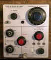
Front view.
-
Top-left view.
-
Bottom view.
-
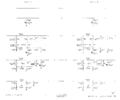
Differential Comparator, initial version
-
Input Attenuators
-
Switching Diagram
-
A-phase (prototype) Type W
-
A-phase (prototype) Type W
-
A-phase (prototype) Type W
-
A-phase (prototype) Type W
-
A-phase (prototype) Type W
Components
Some Parts Used in the W
| Part | Part Number(s) | Class | Description | Used in |
|---|---|---|---|---|
| 6DJ8 | 154-0187-00 • 154-0305-00 | Vacuum Tube (Dual Triode) | dual triode | 067-506 • 111 • 132 • 161 • 310A • 316 • 317 • 502 • 502A • 503 • 504 • 506 • 515 • 516 • 519 • 526 • 529 • RM529 • 533 • 535 • 536 • 543 • 544 • 545 • 545A • 545B • 546 • 547 • 549 • 555 • 556 • 561A • 561S • 564 • 565 • 567 • 581 • 581A • 585 • 585A • 661 • 1A4 • 1S1 • 60 • 2A60 • 63 • 2A63 • 67 • 2B67 • 3A1 • 3A1S • 3A2 • 3A3 • 3A6 • 3A7 • 72 • 3A72 • 75 • 3A75 • 4S2 • 51 • 3B1 • 3B1S • 3B2 • 3B3 • 3B4 • 3M1 • 3S76 • 3T77 • 3T77A • 9A1 • 9A2 • 1121 • 80 • 81 • 82 • 86 • B • O • W • Z • Telequipment D56 • Telequipment S32A • Telequipment D52 • S-311 • Telequipment TD51 • Telequipment S52 • Telequipment S51 • Telequipment Type A • TU-4 |
| 8056 | 154-0417-00 | Vacuum Tube (Triode) | low-voltage Nuvistor triode | 422 • 502 • W • 1S1 • 3A7 • 3S3 • 3T4 • 5T3 • 10A1 |
| 8416 | 154-0413-00 • 157-0116-00 | Vacuum Tube (Dual Triode) | dual triode | 1S1 • 2A61 • 3A8 • 3L5 • W |


