7503: Difference between revisions
No edit summary |
No edit summary |
||
| Line 3: | Line 3: | ||
|series=7000-series scopes | |series=7000-series scopes | ||
|model=7503 | |model=7503 | ||
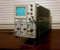
|image= | |image=Tektronix 7503 front in operation.jpg | ||
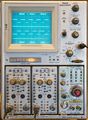
|caption=Tektronix 7503, | |caption=Tektronix 7503, 2×[[7A12]], [[7B53A]] | ||
|introduced=1970 | |introduced=1970 | ||
|discontinued=1972 | |discontinued=1972 | ||
| Line 23: | Line 23: | ||
{{BeginSpecs}} | {{BeginSpecs}} | ||
{{Spec | Bandwidth | 90 MHz with [[7A11]], [[7A16]] (and faster plug-ins); 75 MHz with [[7A12]], [[7A13]], [[7A14]] }} | {{Spec | Bandwidth | 90 MHz with [[7A11]], [[7A16]] (and faster plug-ins); 75 MHz with [[7A12]], [[7A13]], [[7A14]] }} | ||
{{Spec | Fastest calibrated sweep | 5 ns/Div }} | {{Spec | Fastest calibrated sweep | 5 ns/Div }} | ||
{{Spec | CRT | [[T7500|T7500 (154-0608-xx)]], 18 kV total acceleration (+15/-2.96) }} | {{Spec | CRT | [[T7500|T7500 (154-0608-xx)]], 18 kV total acceleration (+15/-2.96) }} | ||
{{Spec | Vertical modes | Left / Alt / Add / Chop / Right }} | {{Spec | Vertical modes | Left / Alt / Add / Chop / Right }} | ||
{{Spec | Trigger Source | Left / Vert Mode / Right }} | {{Spec | Trigger Source | Left / Vert Mode / Right }} | ||
{{Spec | Calibrator | 4 mV to 40 V in five decade steps, 40 mA, 1 kHz ±0.5% }} | {{Spec | Calibrator | 4 mV to 40 V in five decade steps, 40 mA, 1 kHz ±0.5% }} | ||
{{Spec | Outputs | Side panel: Vert signal, +Gate, +Sawtooth; At CRT: Camera power }} | {{Spec | Outputs | Side panel: Vert signal, +Gate, +Sawtooth; At CRT: Camera power }} | ||
{{Spec | Line Voltage | 90-110 V / 104-126 V / 112-136 V / 180-220 V / 208-252 V / 224-272 V, 50—440 Hz }} | {{Spec | Line Voltage | 90-110 V / 104-126 V / 112-136 V / 180-220 V / 208-252 V / 224-272 V, 50—440 Hz }} | ||
{{Spec | Power | Max. 258 W }} | {{Spec | Power | Max. 258 W }} | ||
{{Spec | Weight | 21.3 kg / 47 lb (instrument only) }} | {{Spec | Weight | 21.3 kg / 47 lb (instrument only) }} | ||
| Line 53: | Line 53: | ||
==Pictures== | ==Pictures== | ||
<gallery> | <gallery> | ||
Tek 7503 front.JPG|Front | Tektronix 7503 front in operation.jpg | ||
7503 DSC 0883.JPG|Plug-in bay | Tektronix 7503 front in operation.jpg | ||
7503 DSC 0895.JPG|Plug-in connectors missing sides | Tek 7503cl3.jpg | ||
Tek 7503 front.JPG | Front | |||
7503 DSC 0883.JPG | Plug-in bay | |||
7503 DSC 0895.JPG | Plug-in connectors missing sides | |||
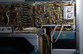
7503 backplane r1.jpg | 7503 backplane PCB [[Repairing 7000-series plug-in sockets#Replacing the connectors with modern equivalents|mid-repair]] | 7503 backplane r1.jpg | 7503 backplane PCB [[Repairing 7000-series plug-in sockets#Replacing the connectors with modern equivalents|mid-repair]] | ||
7503 DSC 0894.JPG|Horizontal amp on top | 7503 DSC 0894.JPG | Horizontal amp on top | ||
7503 DSC 0891.JPG|Vertical amp on the side | 7503 DSC 0891.JPG | Vertical amp on the side | ||
7503 DSC 0888.JPG|Left view, delay cable, CRT | 7503 DSC 0888.JPG | Left view, delay cable, CRT | ||
7503 DSC 0887.JPG|Left view, power supply | 7503 DSC 0887.JPG | Left view, power supply | ||
7503 DSC 0886.JPG|Right view, mains frequency transformer | 7503 DSC 0886.JPG | Right view, mains frequency transformer | ||
7503 DSC 0885.JPG|Readout board | 7503 DSC 0885.JPG | Readout board | ||
DSC 0878.JPG|Right side connector panel | DSC 0878.JPG | Right side connector panel | ||
DSC 0880.JPG|Rear | DSC 0880.JPG | Rear | ||
Tek 7503cl3.jpg | Tek 7503cl3.jpg | ||
Tek 7503cl1.jpg | Tek 7503cl1.jpg | ||
Revision as of 04:56, 9 December 2021

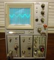
The Tektronix 7503 is a 90 MHz 7000-series mainframe with three module bays, introduced in 1970. It was effectively replaced by the larger-screen 7603 in 1972.
The 7503 project was managed by Phil Crosby, and was supposed to be a 7504 but with one fewer plug-in. The 7503 was Tek's first scope to use a harmonica connector for inter-board wiring. Prior to this, inter-board wiring had either mainly been point-to-point soldered. Other approaches were taken on certain instruments, for example the 7704, in which pins sticking out of the chassis mate with holes in the boards that receive the pins and make electrical contact.
Unlike later three-slot (7xx3) mainframes, the 7503 does supply the +5 V lamp rail, which helps with the contemporary 7A12 plug-in. It also features the 7000-series remote control connector at the rear of the unit.
Key Specifications
| Bandwidth | 90 MHz with 7A11, 7A16 (and faster plug-ins); 75 MHz with 7A12, 7A13, 7A14 |
|---|---|
| Fastest calibrated sweep | 5 ns/Div |
| CRT | T7500 (154-0608-xx), 18 kV total acceleration (+15/-2.96) |
| Vertical modes | Left / Alt / Add / Chop / Right |
| Trigger Source | Left / Vert Mode / Right |
| Calibrator | 4 mV to 40 V in five decade steps, 40 mA, 1 kHz ±0.5% |
| Outputs | Side panel: Vert signal, +Gate, +Sawtooth; At CRT: Camera power |
| Line Voltage | 90-110 V / 104-126 V / 112-136 V / 180-220 V / 208-252 V / 224-272 V, 50—440 Hz |
| Power | Max. 258 W |
| Weight | 21.3 kg / 47 lb (instrument only) |
| Rear connectors |
|
Internals
In addition to two custom Tek ICs, the 7503 uses CA3046 transistor arrays (156-0048-00) in eight places (five on the regulator board). The vertical and horizontal amplifiers are built using discrete transistors.
The 7503 has an X-Y delay compensation network that is activated when the H plugin is an amplifier or a timebase in amplifier mode (see 7000 Series plug-in interface). This network is switched in using a pair of 148-0034-00 miniature relays on the horizontal amplifier board.
Like other 75xx and 76xx mainframes and the 7504, the 7503 has a linear power supply, as opposed to the switchmode supplies used in the later 4-slot mainframes. In addition to the +5 V, ±15 V, ±50 V rails common to the 7000 series, internally (not on the plug-in slots) it has a +75 V output not found in later models, and a +150 V instead of the later +130 V.
The 7503 contains a mercury-based elapsed time meter on the rear of the main interface board.
Pictures
-
-
-
-
Front
-
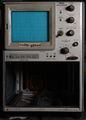
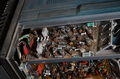
Plug-in bay
-

Plug-in connectors missing sides
-

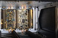
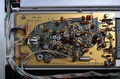
7503 backplane PCB mid-repair
-
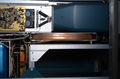
Horizontal amp on top
-
Vertical amp on the side
-
Left view, delay cable, CRT
-
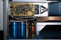
Left view, power supply
-
Right view, mains frequency transformer
-
Readout board
-
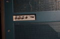
Right side connector panel
-

Rear
-
-
-


Custom ICs used in the 7503
| Page | Model | Part nos | Description | Designers | Used in |
|---|---|---|---|---|---|
| 155-0011-00 | M012 | 155-0011-00 | clock and chop blanking | Les Larson | 485 • 7313 • 7403N • R7403N • 7503 • 7504 • 7514 • 7603 • AN/USM-281C • 7613 • 7623 • 7623A • 7633 • 7704 • R7704 • 7704A • 7834 • 7844 • 7854 • 7904 • 7904A • R7903 • R7912 • 7912AD • 7912HB • 7934 • 7104 • R7103 • AN/USM-281C |
| 155-0022-00 | M036 | 155-0022-00 • 155-0022-01 | analog multiplexer | Gene Andrews | 147 • 148 • 149 • 335 • 468 • 1430 • 1441 • 1461 • 1900 • 1910 • 2220 • 2221 • 2230 • 5223 • 5403 • 5440 • 5441 • 5443 • 5444 • 5A38 • 7313 • 7403N • 7503 • 7504 • 7514 • 7603 • AN/USM-281C • 7613 • 7623 • 7623A • 7633 • 7704 • R7704 • 7704A • 7834 • 7844 • 7854 • R7912 • 7912AD • 7912HB • 7904 • R7903 • 7904A • 7934 • 7A12 • 7A18 • 7A18A • 7A18N • 7B52 • 7B53N • 7D10 • 7D11 • 7D12 • NT-7000 • P7001 |